Hi Ro808
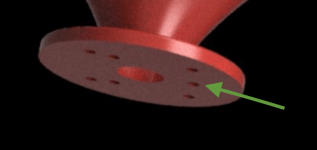
I am aware of the original intention. I just wanted to mention that with the bare driverd without the wavegotmer you have a driver with a ring instead of a hole source. Just curious if this might give more flexibility for wavegront shaping before entering the horn. Or you could get narrow vertikal beam avoiding floor/ceiling reflections. But no idea how we could get a non-round source simulated in ath.
thanks for the other hints! Drivers/AutoIT..
1" version for those brave enough to try it (STLs) - https://at-horns.eu/ext/ST260-KVAR-2022-4.zip


- From the right angle it looks like an ear. A coincidence? I don't think so 😀 (a joke).
- From the right angle it looks like an ear. A coincidence? I don't think so 😀 (a joke).
When listening midfield, what is what one has to anyway, isn’t a more restricted pattern beneficiary to avoid ceiling reflections?Why this over the ST260?
//
If the beamwidth is not constant, there's no "restricted pattern" - the reflections simply contain more of low frequencies and less HF. That's generally not what we want, but with the latest iteration we do the following compromises:
Does it make sense? I don't know - that's to be tried and judged by subjective listeting, I guess.
- there's still very well controlled horizontal directivity (can be as "constant" as we want),
- naturally (?) downward-tilted power response is achieved without making the on-axis/LW response tilted down,
- efficiency is improved a little bit on the lower end,
- the above is achieved at the cost of some vertical beaming.
Does it make sense? I don't know - that's to be tried and judged by subjective listeting, I guess.
Last edited:
This is what the waveguide I have been working on does, so as that of the JBL708, but funnily, the order is reversed in JBLM2. I have not understood their ratio in this, as horizontal reflections are usually hold to be most important, but anyway: they decided so.
The new ST260 could solve some issues in a nice way.
The new ST260 could solve some issues in a nice way.
I'm not sure I follow.[...] but funnily, the order is reversed in JBLM2. I have not understood their ratio in this
It is done to match the vertical pattern of the waveguide to the woofer so there is a smoother directivity match in both planes.This is what the waveguide I have been working on does, so as that of the JBL708, but funnily, the order is reversed in JBLM2. I have not understood their ratio in this, as horizontal reflections are usually hold to be most important, but anyway: they decided so.
What can be seen in M2 is a relatively constant width of the vertical pattern, all the way up, while it is the horizontal which narrows drastically. This is the reversal of the order.
The overall H V size is chosen to match the woofer at the crossover frequency 800Hz. 120H 110V according to Charles Sprinkle somewhere which matches Erin's measurements.
But there is no overall H V size, it varies with frequency as can clearly be seen from the polars. When I had previously explained to myself the significant narrowing of H high frequencies with diaphragm size, I realized it could obviously not be the cause, as the vertical pattern did NOT narrow. This is why it must be reasoned that JBL engineers decided to make the horizontal pattern collapse more towards the top end, it is not a function of the compression driver. And they kept the vertical pattern mich more constant.The overall H V size is chosen to match the woofer at the crossover frequency 800Hz. 120H 110V according to Charles Sprinkle somewhere which matches Erin's measurements.
The physical mouth size and overall aspect ratio.But there is no overall H V size,
Please use some more words to make yourself comprehensible or make the stakes of the argument clear as so they can be addressed properly.It is done to match the vertical pattern of the waveguide to the woofer so there is a smoother directivity match in both planes.
My point was that the pattern of the vertical axis is constant, while the horizontal is narrowing more, to what you replied this was due to pattern width at crossover frequency. There is a clear mismatch, as this does not answer on what I had observed, which was not about pattern width at XO but beyond 6k. The pattern of the M2 waveguide is not truly following an all flat approach, it deviates in the horizontal axis. And I cannot see a reason what this has got to do with pattern width at crossover frequency. Those are relatively independent matters.
- Home
- Loudspeakers
- Multi-Way
- Acoustic Horn Design – The Easy Way (Ath4)
