I also think about it. I do not leave my B1K on all the time -- I turn it on when I want to listen and then turn it off, and I'm sure the bias changes quite a bit over the typical period of a few hours that I have it turned on. I'd love to add some circuitry that would stabilize the bias to a narrower range but can't imagine how it would be done.Yeah, I brought my better meter home from work to double check, same results.
The voltage does seem to have stabilized a bit more, I think I am going to set it at 10V for now and check in a day or two after a couple of long listening sessions. Unless if drifts substantially I will not worry about it anymore.
A bit of drift here or there is no big deal. Just power up and enjoy the music. Don't obsess over a few tenths of a Volt. Obsessing over the bias and constant monitoring detracts from listening pleasure.
It's about the music. 🙂
It's about the music. 🙂

This is a technical website with one end-product being the music. It's not only about the music.A bit of drift here or there is no big deal. Just power up and enjoy the music. Don't obsess over a few tenths of a Volt. Obsessing over the bias and constant monitoring detracts from listening pleasure.
It's about the music. 🙂
Only I know whether I am obsessing or not. I am, regardless, in search of know-how -- is there a way to control bias drift in my B1K. 🙂
This is a technical website with one end-product being the music. It's not only about the music.
Only I know whether I am obsessing or not. I am, regardless, in search of know-how -- is there a way to control bias drift in my B1K. 🙂
A double pour of 15 year old single malt scotch over a single ice cube?
Listen to Euro Techno instead of Vienesse Baroque?
Enjoy life perhaps?
Check it once a week?
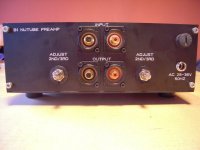
BTW, when I had my B1K built, I requested that the test points be brought out to the back panel. You might want to do that and keep a DMM in there.
There was a conversation about doing that on this thread quite a while ago. So that was yours? How is that working out?BTW, when I had my B1K built, I requested that the test points be brought out to the back panel. You might want to do that and keep a DMM in there.
There was a conversation about doing that on this thread quite a while ago. So that was yours? How is that working out?
I haven't used them... the thing just sounds good. ;-)
Hello wapo54001,
I put my adjustment-pots to the rearpanel. Easy access for adjustments. I added 2mm lab sockets
from Hirschmann (MBI 1) later to measure easily without opening the lid of the case.
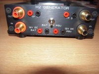
I did the same with my H2-generator. Adjustment pots are at the frontpanel, testpoints at the back.
But I do most adjustments by ear. Then I check with the DMM (to adjust from left to right channel).
My experience is, that once set, you do not adjust a lot anymore. Only if I change any amp, speaker in the chain.
Cheers
Dirk 🙂
I put my adjustment-pots to the rearpanel. Easy access for adjustments. I added 2mm lab sockets
from Hirschmann (MBI 1) later to measure easily without opening the lid of the case.
I did the same with my H2-generator. Adjustment pots are at the frontpanel, testpoints at the back.
But I do most adjustments by ear. Then I check with the DMM (to adjust from left to right channel).
My experience is, that once set, you do not adjust a lot anymore. Only if I change any amp, speaker in the chain.
Cheers
Dirk 🙂
Attachments
Thanks, good to hear. I do understand that setting the bias on the B1K is subjective, first and foremost. I think I remember that my B1K bias changes due to temperature were inconsistent between channels, they did not track each other. My B1K chassis is currently occupied by a BA2018, and I need to get the B1K board back into service so I can experiment with this bias control issue some more.Hello wapo54001,
I put my adjustment-pots to the rearpanel. Easy access for adjustments. I added 2mm lab sockets
from Hirschmann (MBI 1) later to measure easily without opening the lid of the case.
I did the same with my H2-generator. Adjustment pots are at the frontpanel, testpoints at the back.
But I do most adjustments by ear. Then I check with the DMM (to adjust from left to right channel).
My experience is, that once set, you do not adjust a lot anymore. Only if I change any amp, speaker in the chain.
Cheers
Dirk 🙂
stability of settings ( Iq of tube) is having absolutely nothing with circuit per se, everything surrounding tube being of at least 2 magnitude higher in stability;
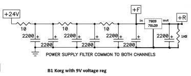
however, circuit can be made more stable, replacing [series resistor+9V1 zener] with 78L09 (1K8 as 5mA shunt between 9V and GND to give at least some load; add there at least 10uF of nice cap)**
but, main factor in stability is funny toob itself - when everything else is stable, you can blame only part itself
** I did post earlier proper schmtc of that arrangement
Thanks for the insight. A question -- do you leave your B1K turned on, or do you switch it on-and-off regularly? If the latter, how much does the bias change from first turn on to fully warmed up, and how audible do you find the drift to be?Hello wapo54001,
I put my adjustment-pots to the rearpanel. Easy access for adjustments. I added 2mm lab sockets
from Hirschmann (MBI 1) later to measure easily without opening the lid of the case.
I did the same with my H2-generator. Adjustment pots are at the frontpanel, testpoints at the back.
But I do most adjustments by ear. Then I check with the DMM (to adjust from left to right channel).
My experience is, that once set, you do not adjust a lot anymore. Only if I change any amp, speaker in the chain.
Cheers
Dirk 🙂
Which resistor are you speaking of -- 270R 3W, or the 7.5K? The 270R gets pretty warm. Could you give a post # for the schematic you mention, please?stability of settings ( Iq of tube) is having absolutely nothing with circuit per se, everything surrounding tube being of at least 2 magnitude higher in stability;
however, circuit can be made more stable, replacing [series resistor+9V1 zener] with 78L09 (1K8 as 5mA shunt between 9V and GND to give at least some load; add there at least 10uF of nice cap)**
but, main factor in stability is funny toob itself - when everything else is stable, you can blame only part itself
** I did post earlier proper schmtc of that arrangement
I've wondered about this part of the power supply. The +/-5% zener tolerance allows the cathode current to be set at considerably different values and as a separate issue I really didn't understand what part this might play in the bias drift. I've got the parts to install 17mA CC sources on tiny pcbs to replace the 475R resistors in the cathode circuit, and was wondering about whether different regulation would also help with the bias drift. Or maybe skip the CC change and install an adjustable regulator to set cathode current at 17mA with the existing 475R resistors and, simultaneously, regulate bias voltages more closely.
Woops🙂
A box of really fun and good s*** arrived just recently. I want to save them in a fine box and hide them over the summer, for the coming fall and winter. But i am not at all sure i can resist the temptation…
😇🤗
Enjoy som of the absolutely Coolest Dudes in the known universe. The Higwaymen. Crankit up!🤗
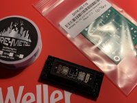
Hehe, Well, and here is some of the pieces of the really good s***:
A box of really fun and good s*** arrived just recently. I want to save them in a fine box and hide them over the summer, for the coming fall and winter. But i am not at all sure i can resist the temptation…
😇🤗
Enjoy som of the absolutely Coolest Dudes in the known universe. The Higwaymen. Crankit up!🤗
Hehe, Well, and here is some of the pieces of the really good s***:
Attachments
Last edited:
Hello wapo54001,
I put my adjustment-pots to the rearpanel. Easy access for adjustments. I added 2mm lab sockets
from Hirschmann (MBI 1) later to measure easily without opening the lid of the case.
I did the same with my H2-generator. Adjustment pots are at the frontpanel, testpoints at the back.
But I do most adjustments by ear. Then I check with the DMM (to adjust from left to right channel).
My experience is, that once set, you do not adjust a lot anymore. Only if I change any amp, speaker in the chain.
Cheers
Dirk 🙂
We didn't bring out the pots brought out to the outside because I am always worried about the possibility of noise being picked up by those wires (antennas)... although he did get and installed the 10 turn pots.
Have thought about drilling a couple of holes on the case to reach the pots from above, but honestly, the thing sounds quite good.
I'll turn it off and on but normally I let it warm up for half an hour before I listen to music. I have not watched for drift.
Thanks for the insight. A question -- do you leave your B1K turned on, or do you switch it on-and-off regularly? If the latter, how much does the bias change from first turn on to fully warmed up, and how audible do you find the drift to be?
Which resistor are you speaking of -- 270R 3W, or the 7.5K? The 270R gets pretty warm. Could you give a post # for the schematic you mention, please?
I've wondered about this part of the power supply. The +/-5% zener tolerance allows the cathode current to be set at considerably different values and as a separate issue I really didn't understand what part this might play in the bias drift. I've got the parts to install 17mA CC sources on tiny pcbs to replace the 475R resistors in the cathode circuit, and was wondering about whether different regulation would also help with the bias drift. Or maybe skip the CC change and install an adjustable regulator to set cathode current at 17mA with the existing 475R resistors and, simultaneously, regulate bias voltages more closely.
here it is
regarding other things you're mentioning - well...... you need to eat way more Porridge and read more books, then start tweaking things only after understanding them
been there, done that more than zillion times, had my share of disappointments, expecting Holly Grail where one can't be found, especially with headbang approach

leave that 475 resistor as is, change what's worth changing
anyway - CCS instead of boostrapped cathode resistor , way to do it properly is:
- make grid fixed to GND potential - 33K to gnd , no voltage divider
- arrange another - negative rail, you need it to connect lower end of CCS there
- remove 475R resistor, put there settable/variable CCS with current range of interest, leave 1000uF in place as is
- that CCS needs to be of greatest possible quality ; you need to know exact current range you wish there; problem is also that needed current is ridiculously small
Attachments
Thank you for the clarifying schematic.here it is
regarding other things you're mentioning - well...... you need to eat way more Porridge and read more books, then start tweaking things only after understanding them
been there, done that more than zillion times, had my share of disappointments, expecting Holly Grail where one can't be found, especially with headbang approach
leave that 475 resistor as is, change what's worth changing
anyway - CCS instead of boostrapped cathode resistor , way to do it properly is:
- make grid fixed to GND potential - 33K to gnd , no voltage divider
- arrange another - negative rail, you need it to connect lower end of CCS there
- remove 475R resistor, put there settable/variable CCS with current range of interest, leave 1000uF in place as is
- that CCS needs to be of greatest possible quality ; you need to know exact current range you wish there; problem is also that needed current is ridiculously small
correction from my side, thinking of both biasing and heater current, I mixed up some things trying to simplify them for posting
roughly 17mA CCS is enough/appropriate ( I=9V1/475R) for heating of tube itself
however, introducing CCS there and changing actual biasing ( setting Iq) of tube is tricky business - Pa pretty much already did it in most practical way
and - resistor connected to firm 9V1 is more than good CCS arrangement per se, for actual needs
Yes, I saw the mixup. Also on your schematic you show three 10R resistor/cap combos and there are only two in the Korg schematic preceding the 270R. And I don't think the 1K8 load resistor is needed -- the heaters draw plenty of current -- unless it serves a different purpose.correction from my side, thinking of both biasing and heater current, I mixed up some things trying to simplify them for posting
roughly 17mA CCS is enough/appropriate ( I=9V1/475R) for heating of tube itself
however, introducing CCS there and changing actual biasing ( setting Iq) of tube is tricky business - Pa pretty much already did it in most practical way
and - resistor connected to firm 9V1 is more than good CCS arrangement per se, for actual needs
My calculations from way back for a 17mA heater current through the 475R plus 41R cathode (=516R) required an ideal supply voltage of 8.77V, and the 9.1V +5% tolerance could up that by quite a bit to 18.55mA, maybe affecting tube longevity (which was the issue that originally made me look at the circuit). Thus my idea of the CCS in lieu of the 475Rs, but an LM317 set to @8.77V in lieu of the 3 watt resistor would accomplish the same 17mA goal.
My concern is how much heatsink would be required to handle the current that heats up a 270R 3 watt resistor as much as it does. Either way I think an LM317 module preset to 8.8V with fixed resistors (for safety), could fit where the 270R is located with the zener removed.
As ZM said in post #7,535, "Pa pretty much already did it in most practical way".
A CCS for the heater will not set the bias for the tube unless a cathode resistor is in place, then it can be filament biased. However having a set bias voltage does not ensure a consistent anode voltage from tube to tube due to tube manufacturing tolerances. Bias voltage adjustment would still be needed to fine tune the anode voltage. But a big problem is that the Vbias for the circuit is somewhere around +2V. Cathode filament bias would provide a negative Vbias, so that would not work.
The 475R resistor in the filament circuit in the existing design is a voltage dropping resistor which combines with the approximately 17mA filament current, drops the 9.1V to 0.6V at the filament, which the minimum filament voltage.
The plate current of the tube is very low, approximately (24V-9.5V)/332kOhm=0.044mA = 44uA.
Probably the simplest way to maintain constant operating voltages is to maintain constant temperature to the circuit, and bias for the long term operating temperature. That would mean keeping the cover on the preamp box, keep the preamp in an area with constant temperature, and adjust bias by quickly opening the box and make the adjustment quickly. But a tiny bit of drift up or down probably wouldn't be perceptible from a sound and listening pleasure point of view.
I have a question about smps. Now, i want to get this smps and put it in the same case as b1k. One note is that case is going to be cnc full aluminium block, and thick wall in between chambers, as an integrated amp with eval 1.
https://www.audiophonics.fr/en/smps...-dalimentation-decoupage-300w-24v-p-6196.html
One issue i have is that i really cannot obtain P089ZB as it would cost me 100$ just to buy it and shipped to me.
Question is, do you presume it would be too much noise? Or should i stick with wall wart smps, and simply have it turned on differently.
Thanks very much for this, it helps a lot in explaining the bias issue which is something I had a vague sense of but really did not understand because I am not a tube person nor electronics by trade.As ZM said in post #7,535, "Pa pretty much already did it in most practical way".
A CCS for the heater will not set the bias for the tube unless a cathode resistor is in place, then it can be filament biased. However having a set bias voltage does not ensure a consistent anode voltage from tube to tube due to tube manufacturing tolerances. Bias voltage adjustment would still be needed to fine tune the anode voltage. But a big problem is that the Vbias for the circuit is somewhere around +2V. Cathode filament bias would provide a negative Vbias, so that would not work.
The 475R resistor in the filament circuit in the existing design is a voltage dropping resistor which combines with the approximately 17mA filament current, drops the 9.1V to 0.6V at the filament, which the minimum filament voltage.
The plate current of the tube is very low, approximately (24V-9.5V)/332kOhm=0.044mA = 44uA.
Probably the simplest way to maintain constant operating voltages is to maintain constant temperature to the circuit, and bias for the long term operating temperature. That would mean keeping the cover on the preamp box, keep the preamp in an area with constant temperature, and adjust bias by quickly opening the box and make the adjustment quickly. But a tiny bit of drift up or down probably wouldn't be perceptible from a sound and listening pleasure point of view.
Of course, I have mixed apples and oranges here by talking about bias and cathode current in the same discussion. Months ago there was a discussion that was started by a couple of very early failures of Nutubes and the question of whether excess cathode current could be the culprit. The 9.1V zener plus the 5% tolerance could allow 18.55mA and still be within zener tolerance and someone mentioned measuring a zener that was above tolerance, and I thought about replacing the 475Rs with CCSs in lieu of either changing the resistor values or selecting a zener well below the nominal 9.1V to achieve the optimal 17mA. I get it that 20mA is the maximum and 18.5 is OK, but I'm just playing here, so why not regulate it to a precise 17.xxmA?
ZM suggests that a voltage regulator in lieu of the 270R would solve the cathode current issue and help stabilize the bias all in one. I like the idea if heat is not an issue. I'm guessing with the zener gone, dissipation through the regulator would be about 40mA @14V = .7W so a TO-220 without heatsink would be enough, or maybe a small heatsink? ("Without a heat sink with an ambient temperature at 50 °C such as on a hot summer day inside a box, a maximum power dissipation of (TJ-TA)/RθJA = ((125-50)/80) = 0.98 W can be permitted.") I would use an LM317 and set the voltage at 8.9V to deliver the 17mA current to the cathodes.
Tubes can be cathode biased or direct biased. In the case of B1 Korg Triode, it is direct biased by the voltage applied to the grid. The Korg triode is directly heated so the filament and cathode are combined. But because this circuit is direct biased, voltage applied to the filament does not affect the bias, as there is no cathode resistor (cathode is grounded). So any changes to the filament circuit will not affect the bias.
The NuTube spec sheet specifies the filament voltage as 0.6V min, 0.7V typ, and 0.8V max. The existing design uses the 475R resistor to drop the 9.1V from the supply to 0.6V at the filament. The voltage measured at T5/T6 is the filament voltage. This assumes that the tube filament draws 18mA. However the filament will draw the current that it wants, and as the tube ages the filament current will increase. The NuTube spec sheet specifies the filament current draw as 16mA min, 17mA typ, and 20mA max. So to maximize tube life, a constant current source in the filament supply could possibly be helpful. But it will not affect the tube bias.
The 270R resistor in the power supply is used in conjunction with the 9.1V zener to drop the 24V to 9.1V. The resistor and zener can be replaced with a 9V voltage regulator but it will not affect the bias. The 9.1V is only for the filament.
As mentioned in my previous post, the bias voltage required for this NuTube circuit is positive. A cathode bias voltage would be negative and therefore not useable for biasing the tube in this circuit. So the filament supply cannot be used in conjunction with a cathode resistor to bias the tube.
The bias voltage, which is the voltage at the tube grid, controls the tube internal resistance which determines the voltage drop across the tube and Iq. A stable tube is a tube with stable Iq. I may be wrong but I think temperature variations may be affecting the tube Iq more than power supply voltage variations at the plate, grid, and filament.
Another thing to check if the voltage at T7/T8 is constantly changing is to also check the power supply and filament voltages (T3,T4,T5,T6). Are they also changing or are they constant?
Last edited:
- Home
- Amplifiers
- Pass Labs
- B1 with Korg Triode