I will install an LM317 at 8.9V for 17mA and then check for voltage stability at the 24V input and the test points. Also replacing the adjustment pots with 10-turn pots.Tubes can be cathode biased or direct biased. In the case of B1 Korg Triode, it is direct biased by the voltage applied to the grid. The Korg triode is directly heated so the filament and cathode are combined. But because this circuit is direct biased, voltage applied to the filament does not affect the bias, as there is no cathode resistor (cathode is grounded). So any changes to the filament circuit will not affect the bias.
The NuTube spec sheet specifies the filament voltage as 0.6V min, 0.7V typ, and 0.8V max. The existing design uses the 475R resistor to drop the 9.1V from the supply to 0.6V at the filament. The voltage measured at T5/T6 is the filament voltage. This assumes that the tube filament draws 18mA. However the filament will draw the current that it wants, and as the tube ages the filament current will increase. The NuTube spec sheet specifies the filament current draw as 16mA min, 17mA typ, and 20mA max. So to maximize tube life, a constant current source in the filament supply could possibly be helpful. But it will not affect the tube bias.
The 270R resistor in the power supply is used in conjunction with the 9.1V zener to drop the 24V to 9.1V. The resistor and zener can be replaced with a 9V voltage regulator but it will not affect the bias. The 9.1V is only for the filament.
As mentioned in my previous post, the bias voltage required for this NuTube circuit is positive. A cathode bias voltage would be negative and therefore not useable for biasing the tube in this circuit. So the filament supply cannot be used in conjunction with a cathode resistor to bias the tube.
The bias voltage, which is the voltage at the tube grid, controls the tube internal resistance which determines the voltage drop across the tube and Iq. A stable tube is a tube with stable Iq. I may be wrong but I think temperature variations may be affecting the tube Iq more than power supply voltage variations at the plate, grid, and filament.
Another thing to check if the voltage at T7/T8 is constantly changing is to also check the power supply and filament voltages (T3,T4,T5,T6). Are they also changing or are they constant?
I suggest monitoring the filament current and voltage first. Are they changing over time or are they constant? Are they within specification?
I wouldn't fix it if it isn't broken, but that is me. 🙂
I wouldn't fix it if it isn't broken, but that is me. 🙂
My diyaudiostore B1K chassis is currently occupied by a BA2018 board so it's a good opportunity to do the two simple changes changes while the B1K board is out loose.I suggest monitoring the filament current and voltage first. Are they changing over time or are they constant? Are they within specification?
I wouldn't fix it if it isn't broken, but that is me. 🙂
If you will only power the B1K with that module, it is substantially more powerful than you need and since it's open it may be quite noisy and the high power may come with high ripple.I have a question about smps. Now, i want to get this smps and put it in the same case as b1k. One note is that case is going to be cnc full aluminium block, and thick wall in between chambers, as an integrated amp with eval 1.
https://www.audiophonics.fr/en/smps...-dalimentation-decoupage-300w-24v-p-6196.html
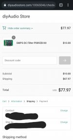
One issue i have is that i really cannot obtain P089ZB as it would cost me 100$ just to buy it and shipped to me.
Question is, do you presume it would be too much noise? Or should i stick with wall wart smps, and simply have it turned on differently.
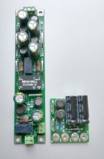
Do you plan to have the power modules in one chamber and audio boards in the other, or does each chamber hold a PS and audio board? If the former, could you take DC power from the Eval-1 PS to power a DC-DC converter for the B1K? You'll only need a small module like the Mean Well SKE10x-24 which has 80mV ripple, 0.5% regulation, and is entirely metal-encased on six sides. You could put it on a pcb with the P089ZB filter components and still have a very compact supply. My own B1K PS board has a converter, two relays, and the filter on all three voltages -- 24,15,-15 -- and still fits beside the B1K inside the small diyaudiostore chassis. I think you could do the whole thing -- PCB from China, converter & filter components for 24V only -- for around $100US.
If you switch both boards simultaneously you might want to include a delay relay on the B1K to avoid quite substantial power on/off pulses from being sent to the power amp. I have the purifi power amp from VTV and had to install a relay on the B1K to avoid nasty thumps at startup.
Attachments
It doesn't matter that it's open, each chamber will contain only one component. And walls will be ~1cm thick.
Recommend me a good step down dc for hypex smps 1200a400?
As for P089ZB, as i said it cost me around 100$ to obtain it (purchase and shipment), so it's a no go honestly, unless you mean print the pcb and populate it (which i don't feel like, i give props to makers and purchase their goods). And meanwell, not so quiet as i had hoped 😁
The part number I gave you comes in three flavors with three different input voltage ranges which, I believe, go from maybe 9VDC up to 70VDC. You need to find out what voltages are available for this purpose from the hypex smps and choose the input voltage appropriately.It doesn't matter that it's open, each chamber will contain only one component. And walls will be ~1cm thick.
Recommend me a good step down dc for hypex smps 1200a400?
As for P089ZB, as i said it cost me around 100$ to obtain it (purchase and shipment), so it's a no go honestly, unless you mean print the pcb and populate it (which i don't feel like, i give props to makers and purchase their goods). And meanwell, not so quiet as i had hoped 😁
Remember, that 80mV is before the post filter and I bet the big smps you had proposed would be much higher, maybe 200mV. Also, there are many other brands, look for one that better suits your purpose.
When I first learned about the P089ZB I asked a question or two online and a fellow spoke up to say he would send me a pcb and most of the parts "just because," and he did that. A lot of fellows who believe in the filter have purchased multiple pcbs from China and I'll bet you could find someone near you who could spare a pcb, and you can order the components from a distributor or maybe someone has a full kit that you could buy at minimal cost. Ask on the P089ZB thread, others have asked before you. Hard to believe a $10 kit will cost you $100 by the time you receive it.
Question about this preamp. I built one of these preamps for a friend with toroidal transformer, Sigma o11 PSU, and upgraded Film caps. I wanted to build another for myself and accidentally bought a chassis that did not come with vent holes.
Can I get away with not having any ventilation or do I need to drill some holes? Any other way to add ventilation if it is needed?

Can I get away with not having any ventilation or do I need to drill some holes? Any other way to add ventilation if it is needed?

Probably better without vent holes. The original B1 Korg chassis in the DIYAudio store had vents and they were removed in the revision to reduce microphonics.
No holes needed in the DIY chassis.
The only holes that make sense, IMHO, are a couple on the top plate to reach the bias pots ( I got the test points wired to rear panel jacks). One of these days when I stop listening...
The only holes that make sense, IMHO, are a couple on the top plate to reach the bias pots ( I got the test points wired to rear panel jacks). One of these days when I stop listening...
78$ for item and shipping. Not 100 my bad. But still too much.Hard to believe a $10 kit will cost you $100 by the time you receive it.
Attachments
Good thing the schematic, parts list, and PCB manufacturing files ("Gerbers") are freely downloadable for everyone. Navigate over to the PO89ZB discussion thread and read post #1. Doing It Yourself might be a lot of fun while also saving you some money.
The Sigma 11 is a linear power supply, not a SMPS.Is this the "Sigma 11" that you are talking about? Sigma 11
You might consider adding Mark Johnson's P089ZB filter as discussed above. The Sigma 11 seems to be a high-power switching supply spec'd at 10uV noise at 30V output with no load but I think Mark has said a load is required for SMPS noise measurements. I believe (from my own experience) that the filter makes a significant difference following an SMPS.
Oh, dear, you are so right -- my bad.The Sigma 11 is a linear power supply, not a SMPS.
hello,
how to increase the gain of this preamp?
is it possible by changing the output resistor?
(i need an extra 12dB)
thanks.
how to increase the gain of this preamp?
is it possible by changing the output resistor?
(i need an extra 12dB)
thanks.
Nutube spec sheet says 14dB typical gain and possibly 17dB if voltage and load resistor increased. But 14dB + 12dB extra = 26dB, is way more than what is possible (17dB).
So what Zen Mod said: a bigger hammer. A regular tube and higher voltage is needed.
A Sony 2SK79 would be a candidate too. 🙂
So what Zen Mod said: a bigger hammer. A regular tube and higher voltage is needed.
A Sony 2SK79 would be a candidate too. 🙂
- Home
- Amplifiers
- Pass Labs
- B1 with Korg Triode