Much thanks - I was targeting around 200mA so this is about right. How big a transformer?I used a 3R3 resistor in R1 to set the current to power my B1k.
Nutube L/R channel imbalance: fix it or is the fix worse than the problem?
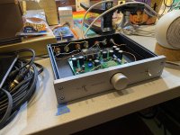
The voltage and current going into the L and R channels of the Nutube in my B1 Korg are identical with the bias set to be identical, but with test tones I measure a 5% L/R imbalance at all volume levels immediately after the NuTube. The grids even look asymmetrical, one left corner noticeably dimmer. The imbalance is audible using test tones, but is not noticeable with music. The best solution may be to stop listening to test tones and play more music, but if wanted to improve performance, how?
My ideas:
1) replace the Nutube. Fixing the source of the problem is the obvious solution, but Nutubes are expensive, desoldering risks ruining the PCB, and a 5% difference may be typical for the Nutube.
2) add an L-pad to the higher channel. Two resistors drops the voltage by 5% without spending anything [else].
3) modify the circuit. Increasing the plate voltage could work, but would cause the two channels to have different distortion profiles. Other changes cause a similar propagation of cane toads, but I’m open to suggestions.
4) Something else? A balance control would be nice but an expensive bit of overkill. Pete Millett designed a negative feedback circuit to compensate for Nutube channel imbalances, but that’s getting to be a different animal entirely.
The 2nd option seems like a cheap and easy solution that can be tested, removed and tweaked quickly. Still, should the L-pad go before the volume pot or at the preamp output? Before the volume pot means I’m unbalancing the input, but padding the output means the loading is pretty different in one channel versus the other. If I’ve done the math correctly, a 2.5k resistor in series and a 940k resistor to ground before the 50k volume pot drops the voltage by 5% but looks the same to the source. Am I close?
It is late down here mate and I am not sure what you are saying, but quickly and probably a bit roughly (pardon me please)...
5% channel difference = 0.4dB difference
OK, not perfect, but I doubt your speakers are matched within 1 dB not to mention 0.5dB
Ok, it all adds up at the end and I understand your worries, but even IF your measurement should be representative (and that's a big IF... into which I really don't want to dig as "who am I to say so"), then nevertheless you are unlikely to be able to hear these 0.4dB difference.
If that can help, I spent some time in listening tests and sessions with various musicians and golden ears and it turns outr even amongst top national ears there aren't many that can differenciate 0.5dB. That was my own limit when I was younger, and I am not a golden ear, but tests revealed I wasn't bad on that very particular exercise which is not really THAT music related...
Bottom line IMHO: no real worries in real life IMHO, eventhough the old engineer in me likes perfections and would like 0.1dB or lower, but perfection isn't B1K... and sounds sterile. Get over it, don't touch it, enjoy the B1K fo what it is (joy machine, precise enough one IMHO) and leave things as they are ;-)
All IME and after a nice botthe of wine
Happy Easter
Claude
PS: IF you run the same measurment in your listening room, you will find that imbalance across frequencies are far worst... not an excuse, I know 🙂
Last edited:
Good to have some perspective. Thanks!I spent some time in listening tests and sessions with various musicians and golden ears and it turns outr even amongst top national ears there aren't many that can differenciate 0.5dB. That was my own limit when I was younger, and I am not a golden ear, but tests revealed I wasn't bad on that very particular exercise which is not really THAT music related...

Clauds answer is a good one. A good dummy check is to make sure that all of the resistors are correct and within tolerance. Anothing thing to consider is that Mr. Pass likes to use two mono volume knobs. Maybe that would be a good option for you?
Thanks for the suggestion! Yes, I would consider this or another volume pot improvement (the Muses volume chip has a balance mode) after I get some hours of listening in on the stock unit.Mr. Pass likes to use two mono volume knobs.
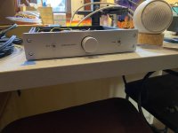
And with that, I’ve screwed on the top cover and am calling it done! The B1 Korg Christmas version in the DIYAudio store chassis. Thank you Nelson Pass for a super fun preamp that’s been on the to do list for much, much too long.
Attachments
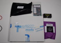
Joining the ranks of my fellow B1K builder/owners today as I received my kit in the mail. Pretty excited to build and eventually listen to it.
I stated the assembly after checking out the various build guides and threads and have encountered my first (likely silly) question.
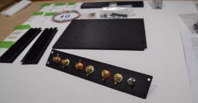
How are most of you assembling the RCA input/output jacks as far as placement of the ground ring connector?
The build guide shows in order: RCA jack > outer insulator (with shoulder) > back plate > inner insulator > ground ring > nut >nut.
That is how I currently have it assembled, but as I was putting them together I was thinking to myself maybe the ground ring is supposed to be between the two nuts instead? I have seen a few build pictures where others have done it this alternate way, but nothing definitive.
Is this simply builders discretion, does it even matter (probably not)? I searched both in the forum and the Internet and have not found anything concrete. Does anyone know the manufacturer of the RCA jacks used, perhaps I could refer to that documentation if I knew what terms to search for.
I stated the assembly after checking out the various build guides and threads and have encountered my first (likely silly) question.
How are most of you assembling the RCA input/output jacks as far as placement of the ground ring connector?
The build guide shows in order: RCA jack > outer insulator (with shoulder) > back plate > inner insulator > ground ring > nut >nut.
That is how I currently have it assembled, but as I was putting them together I was thinking to myself maybe the ground ring is supposed to be between the two nuts instead? I have seen a few build pictures where others have done it this alternate way, but nothing definitive.
Is this simply builders discretion, does it even matter (probably not)? I searched both in the forum and the Internet and have not found anything concrete. Does anyone know the manufacturer of the RCA jacks used, perhaps I could refer to that documentation if I knew what terms to search for.
Attachments
It will conduct the same. I have done it both ways with no ill effects. I like to have only one nut un front if it as it makes it slightly more ergonomic when soldering.
I suppose the washer could help the outer nut loosen. However, still unlikely. I haven't had any issues and I am constantly swapping gear around.
I suppose the washer could help the outer nut loosen. However, still unlikely. I haven't had any issues and I am constantly swapping gear around.
Alright, thanks.
After playing with it for awhile I agree with your take. The one nut seems more than enough to keep them firmly in place, and I am sure the electrical conductivity is just fine.
Also, I don't plan to unplug components too often anyway, so I doubt they would ever come loose. I think I am just over analyzing everything too much and just need to relax and enjoy the build.
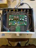
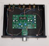
I managed to wrap this project up last night, it wasn't too bad of a build. The kit option makes it a breeze. One small nitpick, if I were to do it again I would use slightly thicker stranded wire for the connections instead of the included thin core solid.
Initial impressions are it sounds good and I don't seem to have the micro-phonic issue under normal use. I did hear it if I tapped the case with the handle of my screwdriver, but with normal operation including listening to music, adjusting the volume control, or switching inputs were all quiet.
I did use the whole length of the Kord triode circuit board's leads though keeping about a 1/2" or so spacing off the main board, so that might help.
I didn't get too much time in for listening yet, I will plan that for this upcoming week.
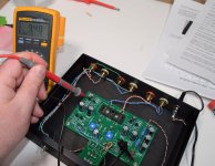
One question I do have, how much warm-up time does it take for the voltage to stabilize using the trimmers and measuring at T7 and T8? I had them set to 9.5V as recommended (after about 20 minutes running) and an hour later there will be a slight drift, usually lower to say 9.47V or so. I then readjusted them back to 9.5V exactly and after another hour or so they drift lower again by a few hundreths.
Initial impressions are it sounds good and I don't seem to have the micro-phonic issue under normal use. I did hear it if I tapped the case with the handle of my screwdriver, but with normal operation including listening to music, adjusting the volume control, or switching inputs were all quiet.
I did use the whole length of the Kord triode circuit board's leads though keeping about a 1/2" or so spacing off the main board, so that might help.
I didn't get too much time in for listening yet, I will plan that for this upcoming week.
One question I do have, how much warm-up time does it take for the voltage to stabilize using the trimmers and measuring at T7 and T8? I had them set to 9.5V as recommended (after about 20 minutes running) and an hour later there will be a slight drift, usually lower to say 9.47V or so. I then readjusted them back to 9.5V exactly and after another hour or so they drift lower again by a few hundreths.
Attachments
I found it to be most stable after 1h, and i've set it then. Hasn't moved since (takes about an hour turned on to heat up, and reach the voltage set each time i power it up, i usually do it in the morning). Also do note that your multimeter has a % margin of error so relax, that is fine 🙂
Thanks for the comment.I found it to be most stable after 1h, and i've set it then. Hasn't moved since (takes about an hour turned on to heat up, and reach the voltage set each time i power it up, i usually do it in the morning). Also do note that your multimeter has a % margin of error so relax, that is fine 🙂
Yeah, I realize the voltage reading is probably not exact at that small of a resolution, but the key takeaway was that in all cases it drifted lower by some small percentage.
If it were a more random reading within say a +/- .05v range it would be one thing, but it seems after several iterations of taking the voltage reading, adjusting the voltage back (up) to 9.50 V, waiting a hour and taking a new reading, in every instance the drift was always going lower. Four or five .03v increments in the same direction start to add up to a 0.15v drift I was just wondering at what point it is safe to adjust it and have it stay put (at least in a relative stable range).
From what i gather, it always drifts no matter the amount of time? Yes, it is ok to set 0.15v more, people set it much higher, it affects the harmonics, but doesn't present a threat to the device. I'm new to the b1k, and haven't had the issue, but you may try to set it at 10v as per papers that came with it suggest, but leave it for couple of hours. Then set bias to 9.5, and leave for couple more hours. If it drifts again, id recheck caps and resistors (which brings me to, if you checked them before populating?).
Also what are your voltage readings on other reading points?
Also what are your voltage readings on other reading points?
All the other test points were within tolerance, I know the supplied wall-wart PSU measures a bit low, like 23.6V but it is stable at that voltage and doesn't drift. That was actually my next thing to try, switching out the PSU for a more robust linear supply.
I did check all the resisters and caps and they were all well within tolerance. I also performed the suggested check of the board at the assembly point where just the power supply components were attached, and measured voltages within spec, again considering the slight lower voltage reading of the PSU.
It may all be nothing as it sounds fine. I might just increase bias to a higher value 9.8V or something and maybe also finding a supply measuring closer to 24V.
There is absolutely no problem at all adjusting at higher voltages - even as high as 14V (with obviously very different caracteristics and if you know what you are doing and why).
Having said that, my B1K doesn't drift at all with time and after nearly 2 years, it is rock stable after a very short warmup period of a couple of minutes.
I know it is quite obvious, but I take it your meter has fresh batteries and perhaps you can confirm your measurment with another meter?
Good luck either way and no worries
Claude
Yeah, I brought my better meter home from work to double check, same results.
The voltage does seem to have stabilized a bit more, I think I am going to set it at 10V for now and check in a day or two after a couple of long listening sessions. Unless if drifts substantially I will not worry about it anymore.
The voltage does seem to have stabilized a bit more, I think I am going to set it at 10V for now and check in a day or two after a couple of long listening sessions. Unless if drifts substantially I will not worry about it anymore.
- Home
- Amplifiers
- Pass Labs
- B1 with Korg Triode