I usually prefer fixed bias, but when I do cathode bias, I use Allen Wright Vacuumstate's trick with the cathodes:
![pp_1c_s[1].gif](https://www.diyaudio.com/community/attachments/pp_1c_s-1-gif.1043813/ "pp_1c_s[1].gif")
Use individual cathode resistors to ground, then connect the cathode bypass capacitors together and then ground through a single resistor of around 14% of the value of the single cathode resistor. This will reduce IMD and 3rd harmonic as well (there are some tests performed on this forum).
Use individual cathode resistors to ground, then connect the cathode bypass capacitors together and then ground through a single resistor of around 14% of the value of the single cathode resistor. This will reduce IMD and 3rd harmonic as well (there are some tests performed on this forum).

Thanks, jacques antoine and koda. Very informative. Hopefully my AB-Q will survive my more benign application well enough. Zintolo, thanks for your reminder of the ”Allen Wright bias trick”. I should try it sometime.
I did that on a couple of the 6AS7G push pull setups I built, it worked well. I eventually went over to cross-coupled garter bias and went back to traditonal bypass cap orientation.

The connection of the 6.3V center tap depends on the rest of the circuit, voltages, and the filaments that use them,
versus the voltages on the cathodes.
Examples just for conceptual illustration:
1. All cathodes DC voltage less than 50V.
Ground the center tap (unless the filament to cathode voltage rating for the tube is very low).
2. Some of the cathodes DC Voltage is more than 100V (and the tube filament to cathode voltage rating is 100V or less).
A concertina phase splitter can have an elevated cathode, and so elevate the center tap too.
3. If the signal swings cause the cathode to rise far above its quiescent voltage, then more accurate inspection of the tube filament to cathode voltage specs, and the peak voltage of the cathode needs to be accounted for.
I am not sure I asked my question right.
Unlike the posted schematics, the transformer I will use for the SPP has a 6.3V secondary with a center tap.
Do I need to connect this CT to GND or do I leave it flapping in the breeze?
BTW I checked a bunch of old Mullard schematics and all connect this CT to GND.
Just beeing careful with my first tube build...
The center tap would connect to the 30k resistor on the bottom right of the schematic instead of the 6.3V tap
I get it know. The 150K/30K voltage divider yields ~50V to be applied to CT.
Found also some info on ValveWizard.
Found also some info on ValveWizard.
Attachments
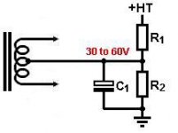
If you build an SPP on the Tubelab board one side of the 6.3 volt will be connected to the junction of the 30K and 150K resistors mounted on the board. In that case if your transformer has a centre tap on the 6.3 volt winding just insulate it. If you are building point to point or turret boards or similar you may connect the centre tap to the junction of the resistors.
S.
S.
From what I've read, it seems beneficial to take advantage of that center tap.
I'll check tonight if the Tubelab board can be 'doctored' without too much damage.
I'll check tonight if the Tubelab board can be 'doctored' without too much damage.
There's no practical advantage to using the C.T. as far as I know.
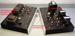
Want a quiet (low hum) SPP?
-Don't use a cramped chassis.
-Keep the P.T. as far away from the OPTs as much as possible.
-Position the OPTs at right angles to the P.T.
-Use a choke in the power supply and keep it at right angles to the P.T. and a few inches away.
Both of my SPP builds were so quiet they could be used to drive 100dB horns if I'd wanted.
Last edited:
Steve,
My OPTs are toroids, not sure how to calculate a right angle between them and the PT 🤓 .
The choke is already here as well as most of the components; I noticed a dedicated L1 choke connector on the board.
If it works as expected, I am planning a 2U 19'' chassis with all transformers inside.
I will only do the CT mod if I'm not pleased with the plain vanilla build.
Steve,
On George's web site that the recommended value for R3 is indeed 10K 1W (see Parts List), not 30K 1W as in the posted schematics.
The heaters will only be elevated by ~19V instead of ~50V. Does it really matter ?
On George's web site that the recommended value for R3 is indeed 10K 1W (see Parts List), not 30K 1W as in the posted schematics.
The heaters will only be elevated by ~19V instead of ~50V. Does it really matter ?
This what George wrote in post no. 23:
I disagree with reducing the value of R3. The older 12AT7's have a H-K breakdown voltage spec of 90 volts. The cathode of the second section can be nearly 90 volts depending on the B+ being used. The cathode of the first section is near ground potential. The heaters need to be biased up to somewhere between zero and the cathode voltage on pin 3 of the 12AT7. Ideally this should be about halfway between the two voltages, but some old tubes seem to exhibit hum of the voltage is too high. 30K was the best compromise in my testing many years ago with lots of different 12AT7's and 6201's. 10K might be fine with a mil spec 12AT7WA or other new production tube though.
I disagree with reducing the value of R3. The older 12AT7's have a H-K breakdown voltage spec of 90 volts. The cathode of the second section can be nearly 90 volts depending on the B+ being used. The cathode of the first section is near ground potential. The heaters need to be biased up to somewhere between zero and the cathode voltage on pin 3 of the 12AT7. Ideally this should be about halfway between the two voltages, but some old tubes seem to exhibit hum of the voltage is too high. 30K was the best compromise in my testing many years ago with lots of different 12AT7's and 6201's. 10K might be fine with a mil spec 12AT7WA or other new production tube though.
Back on Allen Wright suggestion, these are the results without that 14% resistor:
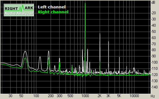
And then with that resistor:
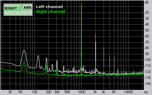
Notice how sidebands and odd harmonics are reduced.
And then with that resistor:
Notice how sidebands and odd harmonics are reduced.
Hi everyone, I need some more specs for my output transformers from toroidy. I told them push pull but I guess they missed that part.
This is the message I received:
I need additional information for output transformer:
1) Expected supply voltage of the system.
2) Maximum anode current
3) Amplifier power
4) Input impedance Ra (for SE) or Raa (anode - anode for PP)
5) Output impedance (4 Ohm / 8 Ohm or others)
6) System type - PP or SE
7) UL taps - what%
What I think I have so far:
1) 120v
2) ?
3) ?
4) Raa?
- I specified primary impedance: 7.6k ohm, is this different?
5) 8 for 8 ohm speakers?
6) PP
7) I plan on using UL mode mostly or only so what % should I go with?
Thanks for you guys' help.
Also, off topic but I'm also getting a PT for my little bear t11 and I'm having trouble figuring out the current rating for the 200-0-200v winding. I'll be running (3) 12ax7's and a 6c4p-ev.
- Home
- Amplifiers
- Tubes / Valves
- Easy DIY tube amp