I will update GitHub, but still working to update documentation and I'm slow, very slow. 🙄
As Tim said, 2oz Cu make sensible sonic difference compared with 1oz, mainly because coil resistance will be lower.
Regards,
Tibi
As Tim said, 2oz Cu make sensible sonic difference compared with 1oz, mainly because coil resistance will be lower.
Regards,
Tibi
Documentation is hard work. Always had to do it for the software I wrote. Hated it. But there's a special pleasure in doing a good job of something you don't like doing 🙂I will update GitHub, but still working to update documentation and I'm slow, very slow. 🙄
As Tim said, 2oz Cu make sensible sonic difference compared with 1oz, mainly because coil resistance will be lower.
Regards,
Tibi
2oz it is then...
@ed linssen
Thank you ! The ideal bridge mentioned here https://www.diyaudio.com/community/threads/ideal-bridge-rectifier-gb.333844/page-21#post-6212303 will work. To use active power supply, which come with this project, you need a smd bridge similar with Saligny Standard.
Hi Tibi,
What is the difference between the 'ideal bridge' mentionned on de first line, and the one used in the 'active power supply'? I thought they were technically the same?
regards,
Ed
Attachments
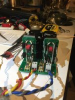
Nice implementation ! 👍
The obvious difference is that one is THT - open source -while other one is SMD - commercial. The SMD one will fit pcb better.
Both will work very well.
Regards,
Tibi
The obvious difference is that one is THT - open source -while other one is SMD - commercial. The SMD one will fit pcb better.
Both will work very well.
Regards,
Tibi
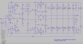
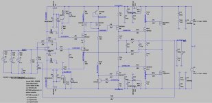
In the last days, I was playing with a very high power Q17-ludicrous. 😉
This will be able to deliver at least 600W/8hm, 1200W/4ohm, 2400W/2ohm.
I already made few high power Q17 using Exicon double die laterals, but this is a different approach due very high capacitance of Fairchild mosfets.
Please take this as an exercise. In real world, some parts must be adjusted. It will simulate ok, but practical implementation will be a challenge.
Regards,
Tibi
Attachments

Hi Tibi,
with your knowledge of quad power stages would you be able to extract the built in protection against shorts that is inherent in these amps?
im after some help with this as I want to add a robust protection to another amp design (L20SE) so I can run it safely on a pair of ESL63’s.
I’ve built the amps but have since found out about this problem with blowing unprotected amps.
As you know these ESL’s put a near short on the amp output if they drop into protection mode.
if it’s very major I’ll need to scrap the project and go with a quad made amp but these are fully built now as mono blocs so would like to use them.
Thanks for the confirmation, Tibi!Nice implementation ! 👍
The obvious difference is that one is THT - open source -while other one is SMD - commercial. The SMD one will fit pcb better.
Both will work very well.
Regards,
Tibi
Regards,
Ed
I have created a GB thread.
https://www.diyaudio.com/community/...phile-approach-group-buy.384647/#post-6981530
Regards,Tibi
https://www.diyaudio.com/community/...phile-approach-group-buy.384647/#post-6981530
Regards,Tibi
Hello Tibi,In the last days, I was playing with a very high power Q17-ludicrous. 😉
This will be able to deliver at least 600W/8hm, 1200W/4ohm, 2400W/2ohm.
I already made few high power Q17 using Exicon double die laterals, but this is a different approach due very high capacitance of Fairchild mosfets.
Please take this as an exercise. In real world, some parts must be adjusted. It will simulate ok, but practical implementation will be a challenge.
Regards,
Tibi
this is a very interesting approach that you are using in your high power amplifier. I have simulated this for critical issues and it behaves more stable than the Q17. Here I compare the Q17 with the new variant with only one pair of power stages. What I still don't understand is why the amplifier needs +- 70V, the simulation stops at a lower voltage.
I overlooked it, of course it works fine with lower voltage when R25 is adjusted.
Regards Tim
Attachments
Last edited:

Hello Andrew,Hello Tibi
greetings i am wanting to make this amplifier input 1uf cap i am not sure if i can use this cap.
warm regards
Andrew
the MKP10 from Wima is a good capacitor for current smoothing. This capacitor is suitable as C7, if a FKP capacitor is installed in parallel. I find the combination of the MKP10 and a 100nF FKP1 a good economical solution.
Regards Tim
Hi Tibi!High power need high voltage.
Regards,
Tibi
Can I expect more profit, soundwise,
with my ESLs, switching from the one fet to the two fet version, keeping the psu voltage at around 50 volts dc? I don’t need the power gain.
And what changes do I need to keep the machine at about 100watts as is?
Regards,
Ed
Hi Ed,
It will perform better ? For sure, Yes.
It will sound better ? Maybe, because depends on your source, your cabling, your room etc.
Adding more output devices will decrease amplifier output impedance and therefore increase amplifier capability to deliver more current in a low impedance.
Adding more output devices will make amplifier "more powerful" at lower impedances and increase his capability to drive complex audiophile speakers , including ESL.
For example at same +/-50V and 1KHz, an amplifier (here I do not talk about Q17) may have:
1. With one pair
- 100W in 8ohm
- 120W in 4 ohm
- 120W in 2 ohm
2. With two pairs
- 100W in 8ohm
- 180W in 4ohm
- 300W in 2 ohm
Having an amplifier with very low output impedance make sense even you have small bookshelf speakers.
Q17 achieve this by using high transconductance mosfets. One pair already drive a wide range of speakers very well. Two pairs is for audiophiles who look for the best at given price.
Regards,
Tibi
Hi Tibi,Hi Ed,
It will perform better ? For sure, Yes.
It will sound better ? Maybe, because depends on your source, your cabling, your room etc.
Adding more output devices will decrease amplifier output impedance and therefore increase amplifier capability to deliver more current in a low impedance.
Adding more output devices will make amplifier "more powerful" at lower impedances and increase his capability to drive complex audiophile speakers , including ESL.
For example at same +/-50V and 1KHz, an amplifier (here I do not talk about Q17) may have:
1. With one pair
- 100W in 8ohm
- 120W in 4 ohm
- 120W in 2 ohm
2. With two pairs
- 100W in 8ohm
- 180W in 4ohm
- 300W in 2 ohm
Having an amplifier with very low output impedance make sense even you have small bookshelf speakers.
Q17 achieve this by using high transconductance mosfets. One pair already drive a wide range of speakers very well. Two pairs is for audiophiles who look for the best at given price.
Regards,
Tibi
Thank you for this very detailed answer.
My second question was:
"What adjustments are needed to let the double output version work on say 48 to 50 Volts?"
So when the same psu is used as the single paired mosfet amp. Or is this not a good practice? This because of not needing all the power and economical perspective too....
Regards,
Ed
Thanks Tibi,The single part that must be adjusted is R25.
Regards,
Tibi
That's what I did read in earlier posts. I wonder how I should calculate the correct resistance in my case. (48-50Volts DC on the dual mosfet pair version)
Regards, Ed.
Btw, are you willing/able to supply me with the needed 2cs2240/2sa970 maybe?
Can't find those anywere......
Last edited:
- Home
- Amplifiers
- Solid State
- Q17 - an audiophile approach to perfect sound