
Yes, I mistakenly referred to the 78 reg as "adjustable" when I meant to refer to the "ref" pin (ground) as being adjustable by lifting it with the addition of a zener. In both cases of the 78xx and lm317 regs, they have been susceptible to failure when trying to trick use them above rated input / output differetial of 37v with ref pin directly to ground. I haven't found a reliable way to keep that from sporadically happening and its the main weakness of that type of Vreg.
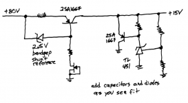
This is pretty close to what I was after and thanks for the practical example circuit.The Vardebedian topology gives tremendous attenuation ("PSRR"), if that is important.
_
I like the Vardebedian topology for this specific task, but you must remember: The power dissipated by the original series resistor is now the same in any linear regulator configuration we can think of, but this V regulator should have a great PSRR. Heatsinking will probably be necessary.
Plenty of PCB mounted (i.e. not chassis mounted) heatsinks can easily dissipate 3.5 watts without roasting the semiconductor junctions. Suggest you confine your search to the ones made by AAVID Thermalloy, their docs seem to contain the most realistic thermal information. Or, since the topology unavoidably contains ballast resistors, you can just connect two (ballasted) transistors in parallel, each on their own less-macho, less-expensive heatsink, and be confident that they will share the current and split the power dissipation, exactly fifty fifty.
All good suggestions High PSRR and low linear impedance is what I'm after. A well implemented 3 pin series reg can do alot, but its lousy at dampening reflected / reactive energy and its critical to get it working in the middle of its "fully on" state of operation.
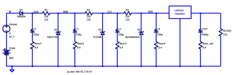
The dissipation of dropped series voltage isn't so nuch concern if the resistive element doesn't add noise and isn't being run close to its max thermal capacity. I don't believe in running a power resistor more than 1/3 its rating and prefer thick film elements to wire wound as they can be had in to220 case. The small 10w Dale type ww resistors are nice too and very reliable for ballast R. Keeping an active zener out of the power handling path is my main goal, as they are very noisy, loose and non-linear.
The dissipation of dropped series voltage isn't so nuch concern if the resistive element doesn't add noise and isn't being run close to its max thermal capacity. I don't believe in running a power resistor more than 1/3 its rating and prefer thick film elements to wire wound as they can be had in to220 case. The small 10w Dale type ww resistors are nice too and very reliable for ballast R. Keeping an active zener out of the power handling path is my main goal, as they are very noisy, loose and non-linear.
Mark, where did you find the info on this topology? I searched and came up with nothing. I can see the theory of operation of separate components but would like to dig deeper into the interaction of it all. Assuming a healthy beta of series transistor is needed. The amplified zener ref shunt makes sense in its topology.The Vardebedian topology gives tremendous attenuation ("PSRR"), if that is important.
_
For dampening reflected / reactive energy I think it will be hard to beat the Bybee Music Rail approach. The load current actually makes the regulator regulate better (since closed loop Zout is proportional to (1/gm) and gm rises when load current rises).
One way to think about the TL431 shunt reference IC, is to imagine it as an NPN bipolar transistor whose VBE(on) is exactly 2.495 volts and whose gm is incredibly high: greater than five million micromhos ( >5 Siemens). Unfortunately, neither T.I. nor any of its competitors sell a "complementary TL431", i.e., a PNP bipolar transistor whose VBE(on) is exactly -2.495 volts and whose gm is enormous.
And (I claim) that is one reason why you seldom see the Vardebedian topology actually deployed in the field: in the applications where it might be appropriate, people almost always want bipolar supplies with plus and minus 15 volts DC. IF we had a "complementary TL431" to install within the negative regulator, it would merely be the dual, the complement, of the positive regulator. But there is no such IC. Which means the negative regulator circuit is forced to be different than the positive regulator circuit.
Apparently it's either difficult, or annoying, or aesthetically revolting, to implement bipolar regulators this way. Thus very few people do.
Actually, I prefer a normal zener diode over the TL 431, so all is not lost. Adding the transistor to the zener is what I find most useful. I realize that some here have had problems with zener diodes, but I use them all the time. Perhaps there are serious differences between brands.
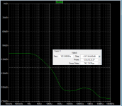
Hi Profiguy,Thats interesting. I'm seeing around -90 dB distortion components in the 15V rails to servo and input fet pairs with a steady state 4 ohm load @ 10W..It gets worse with higher current peaks drawn from 80V main output rails. The fact that isolating the PS rails of the fet input sections made it sound significantly better is a sign theres junk entering the front via the PS.View attachment 1027803
What did you end up with? I have the A21 in black would be interested in doing the same modification that you might end up with. However I cannot find schematic for the amp. is it possible that you will share? Regards SkovvokS (fsko021@gmail.com)
Hi, sorry to resurrect this thread after years but I found it very useful. This is because I intend to buy an A21 to drive my Thiel CS2.4, notoriously a difficult load because their impedance oscillates between 2.5 and 3.0 ohms for a good part of the audible spectrum. I ask then if the problem you recorded of increased distortion related to sudden current requests should I expect only if I 'turn up the volume' or also at low listening levels, which I do in 95% of cases?Been doing some poking around and measuring in my Parasound A21. Reason for this is higher odd order HD at lower load impedance (4 ohms). Mind you this amp already has low THD but odd order HD dominates. Its a fabulous sounding amp but it has some difficulty retaining its composure at high current demand peaks.
The key to getting the best overall performance from the A21 is to bias it a little colder. I feel that stock bias is too high on this amp. Reducing it slightly eliminates the strain on the last drive stage section, which is done with a complementary mosfet circuit. Parasound specifies 15mV across each emitter resistor but I feel this is too much once the amp warms up. I set all of my A21s (I have 3 of them along with a JC5) to roughly draw a total of 200W of AC power draw at idle after warm up. Thats roughly with a 10mV bias setting across the emitter resistors. At a 15mV setting, the amp will end up drawing 270W at idle warmed up. The sound is a bit more midrange focused at this bias setting but more shy from a low end impact perspective.
The trick to setting bias on these A21s is to use a watt meter to measure AC load from either channel with the bias pulled back all the way. This allows for precise bias setting on both channels.
One thing to observe is the A21 uses a fast warm up cycle by increasing bias at cold turn on. This means the amp will draw more initially than warmed up, which isn't common on other typical class AB amps which do the opposite. You have to let the amp sit for at least 30 min before setting final bias under warmed up conditions. This involves quickly reducing bias after the 30 min and brining each channel back up to result in a total of 200 - 220 W draw warmed up. If you don't do this quickly, it will put the anp back into warmup phase.
Once that's all set and done, you'll have no issues with current delivery into low impedances. Theres a rumor stating the older A21 sounds better than the newer A21+ version. Not sure if that's true, but in the end, my A21s sound closer to my JC5 once the bias is set up correctly.
I would say the way you load a zener greatly dictates its reliability, not to mention the amount of noise it generates.Actually, I prefer a normal zener diode over the TL 431, so all is not lost. Adding the transistor to the zener is what I find most useful. I realize that some here have had problems with zener diodes, but I use them all the time. Perhaps there are serious differences between brands.
What are you're thoughts on biasing the A21 a little bit colder? It seemed to make a big difference in overall performance when I dropped the bias on my A21s. They all idle around 110 deg F without much temp rise playing them very loud, maybe up to 15 degrees higher temps. Interestingly the distortion levels dropped a little across the entire bandwidth.
@Markw4 I only had brief conversations with him on here. He replied above to my regulator questions. I believe he's one of the best modern amp designers who doesn't beat around the bush about pointless crap.
My findings concerning bias related tonal differences in solid state AB applications isn't that far fetched. Alot of amps behave differently at varying levels of bias, especially high bias AB designs. There are of course feedback related effects which show themselves at varying levels of bias.
On the HCA1500 amps, just changing the feedback resistor to a higher grade Holco piece actually makes a noticeable difference in low level detail. Just by changing a lousy little 47k resistor you can hear better performance. There is another mod which consists of installing lower value resistors in the mosfet driver stage, improving bass quality.
The A21 has a similar drive circuit as the HCA1500. It may also benefit from some changes in that area.
Thank you, unfortunately I haven't the necessary skill to do so. Anyway, in general, do you think that A21 is suited to drive a difficult load as that of the Thiel CS2.4, as below?The key to getting the best overall performance from the A21 is to bias it a little colder. I feel that stock bias is too high on this amp. Reducing it slightly eliminates the strain on the last drive stage section, which is done with a complementary mosfet circuit. Parasound specifies 15mV across each emitter resistor but I feel this is too much once the amp warms up. I set all of my A21s (I have 3 of them along with a JC5) to roughly draw a total of 200W of AC power draw at idle after warm up. Thats roughly with a 10mV bias setting across the emitter resistors. At a 15mV setting, the amp will end up drawing 270W at idle warmed up. The sound is a bit more midrange focused at this bias setting but more shy from a low end impact perspective.
@andreaemme I think the A21 would do just fine with that load. I'd stay away from the first generation model A21 with the 80V main filter caps. These were eventually upgraded to the 100V caps because the rails were running right at 80V on the A21, so filter caps wouldn't last long run right at max voltage all the time. Otherwise they're very reliable.
- Home
- Amplifiers
- Solid State
- Better V-reg for Parasound A21 amp?