Been doing some poking around and measuring in my Parasound A21. Reason for this is higher odd order HD at lower load impedance (4 ohms). Mind you this amp already has low THD but odd order HD dominates. Its a fabulous sounding amp but it has some difficulty retaining its composure at high current demand peaks.
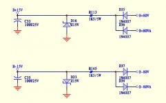
I traced much of the "problem" to the dirty vreg solution of a simple 1.5k 5W resistor feeding 15V zeners to drop 65V (!!!). Along with producing tons of heat (running at 250 degrees F !), it allows alot of garbage to modulate down into the VAS and introduce distortion. I injected external clean +/- 15V into the first input stage and it made a huge difference in sound.
Any suggestions of a better approach to regulating the +/- 15V ie. mosfet series reg or is it smarter to run separate standalone supplies instead?
Even a simple 317/337 series vreg would be way better than the dirty garbage zener approach, but there aren't any 3 terminal regs I'm aware of capable of surviving the initial B+ difference at turn on. I would like to do something like separate op amp corrected series regs for both channels.
Any suggestions?
Attachments
The R+ zener combo is the DC servo PSU arrangement, not? The front end is powered by a cap multiplier.
It seems you have the equipment to measure the harmonic profile; Parasound connects the midpoint of the driver FET source resistors always to the output (Self EF II arrangement). It could be very interesting to compare harmonic profiles with and without this connection.
Disconnecting this midpoint has as good as no impact to stability according my real live experience on a very comparable amp.
Last edited:
Other idea: RC combo in power rails to FET drivers, to isolate them a bit from the high current rails to the output stage. I use 4R7 + 10kuF in each rail very close to the driver FET’s.
Ive considered somewhat of a brute force approach with a big RC you suggest. This amp does use some rather miniscule filtering in places.
Thats interesting. I'm seeing around -90 dB distortion components in the 15V rails to servo and input fet pairs with a steady state 4 ohm load @ 10W..It gets worse with higher current peaks drawn from 80V main output rails. The fact that isolating the PS rails of the fet input sections made it sound significantly better is a sign theres junk entering the front via the PS.The R+ zener combo is the DC servo PSU arrangement, not? The front end is powered by a cap multiplier.
It seems you have the equipment to measure the harmonic profile; Parasound connects the midpoint of the driver FET source resistors always to the output (Self EF II arrangement). It could be very interesting to compare harmonic profiles with and without this connection.
Disconnecting this midpoint has as good as no impact to stability according my real live experience on a very comparable amp.
Last edited:
Looks like those can't deal with 65V input differential. Interesting products though.Monolithic devices maybe swap to Sparko lab drop in V reg?

Another thing you can do is replace the 5 watt dropper resistors (1.5 Kohms) with 45 milliamp constant current sources. The CCS's will dissipate 3 watts, so put their pass transistors on some appropriately sized heatsinks. CCS output current is small so you can use either a power-BJT or a power-MOSFET for the pass transistor, whichever you prefer.
Voila, now you've got a shunt regulator (Zener + CCS) with damn excellent supply noise rejection. Each CCS requires about 5-7 electronic components plus a PCB mounted heatsink.
Voila, now you've got a shunt regulator (Zener + CCS) with damn excellent supply noise rejection. Each CCS requires about 5-7 electronic components plus a PCB mounted heatsink.
I
Looks interesting as a solution. 45 dB of noise reduction isn't that much at lower frequencies and I'm concerned about the reliability if run the same way as a lower voltage 3 pin reg with a large voltage reference. They're risky to implement because the startup voltage drop will exceed the safe range until the regulator turns "on" fully.
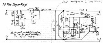
That is a promising reply. I had some ideas about this very concept, which I believe is the cleanest form of DC for audio. 2 x I (source) - 1 x I (sink) = 1 x I (net). I first heard about this when I looked through some old tectronix scope manuals. Allen Wright did a big writeup on this (although a bit over the top OCD), calling it a "super reg" - very complex but probably the best transient response of any reg I've seen.Another thing you can do is replace the 5 watt dropper resistors (1.5 Kohms) with 45 milliamp constant current sources. The CCS's will dissipate 3 watts, so put their pass transistors on some appropriately sized heatsinks. CCS output current is small so you can use either a power-BJT or a power-MOSFET for the pass transistor, whichever you prefer.
Voila, now you've got a shunt regulator (Zener + CCS) with damn excellent supply noise rejection. Each CCS requires about 5-7 electronic components plus a PCB mounted heatsink.
I don't want to retain a zener shunt, mainly because they are inherent white noise generators. I'd rather use another fet with resistor and some LEDs as a current sink.
Attachments
The thing which really frustrates me is Parasound put all this effort into the design of the A21 and skimped on a basic PS circuit that allows a whole bunch of noise back into the front end. I know they have a budget to adhere to but this was a rather important area to pay attention to that makes a HUGE difference in SQ. Maybe they just didn't want this amp to compete with their JC line, but it does have the traits of a very musical yet accurate amp with alot of current reserve.
Unfortunately the zenee drop regulator is very bad at keeping the voltage fluctuations of the B+ rails from getting back into the front end. When this amp is running in the class A biased portion of its output, it sounds almost tube like and extremely open, neutral and clear. Once it needs to push some current outside of the high bias area, it starts getting a bit more gritty and rough sounding, especially with lower impedance loads and when the AC line volrage is contaminated with daytime noise ie. motors, compressors, dimmers, etc. This isnt coming from the output stage as i confirmed with my measurements. I can tell this from the multitudes of my amplifier building endeavors, trying to decipher symptoms I was hearing.
The A21 would be (dare I say) the near perfect amp if it wasn't for the (lack of) regulator issues and the sketchy Chinese build quality induced problems. The JC5 is cleary a better sounding amp and probably has extensive front end regulation, but I'm not forking over 6k$ for one, plus I have five A21s scattered throughout my home and I'm determined to fix the "zener regulator flaw" in all of them.
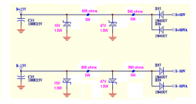
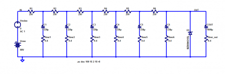
Sutherland Engineering proudly uses brute force when they attack this same problem in their nosebleed priced phonostages. They install an RC-RC-RC-RC-RC-RC ladder network between the rectifier and the shunt regulator (zener diode). Since you know in advance that the sum of the series R's should be equal to or less than 1.5K, just set Rindividual = (1500 / N) and set Cindividual = (as much as you can afford).
Here's what it looks like for N=6 segments, using one of (THESE) $1.22 capacitors {qty=12 pricing} in each stage. You might or might not want a bleed resistor across the output, for the safety of service personnel.
_
Here's what it looks like for N=6 segments, using one of (THESE) $1.22 capacitors {qty=12 pricing} in each stage. You might or might not want a bleed resistor across the output, for the safety of service personnel.
_
Attachments

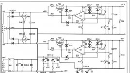
And if you don't like Zener diodes applied as shunt regulators, you can use an amplified zener (below), a TL431, a Salas Ultra-BiB, or an opamp + discrete transistor as the shunt. Many possibilities. [thought experiment / homework problem: install a Sziklai pair]
CF is an optional component which attempts to filter out most of the noise generated in the Zener diode.
_
CF is an optional component which attempts to filter out most of the noise generated in the Zener diode.
_
Attachments
I can see how this can turn into an over engineered solution to a basic issue. The ladder RC has potential and I've seen it work well in certain applications not requiring tight regulation. My main goal is to get rid of the B+ fluctuations at the diff input pairs. A CCS with a fet feeding a TL431 based shunt appears to be the best "hifi" solution. Im pretty sure some of that looseness is desirable to many ears that like more H2 in their audio. Upon closer inspection, the JC5 amp uses separate supplies for the input stages (as expected).
I remember the old phase linear amps that didn't have a CCS or current mirror in their front end, which sounded bad when compared to a modern design with diff input pair, current mirror and Szlklai pair. Just a CSS loaded input made a massive difference in these amps, even with a loose R fed zener supply. My standards are much higher these days having heard a few well designed amps. Even a cheap LM3886 chip amp with BJT gain stage done right blows the old junk out of the water.
I remember the old phase linear amps that didn't have a CCS or current mirror in their front end, which sounded bad when compared to a modern design with diff input pair, current mirror and Szlklai pair. Just a CSS loaded input made a massive difference in these amps, even with a loose R fed zener supply. My standards are much higher these days having heard a few well designed amps. Even a cheap LM3886 chip amp with BJT gain stage done right blows the old junk out of the water.
Reduce the value of "N" in the N-stage ladder, until you feel it is no longer over engineered. A classic tradeoff of performance vs complexity. Or if you prefer, performance vs cost.
Also consider the question "which approach is the most forgiving / most bulletproof, in the hands of someone who doesn't quite know how to calculate component values, or to analyze circuit performance?"
Also consider the question "which approach is the most forgiving / most bulletproof, in the hands of someone who doesn't quite know how to calculate component values, or to analyze circuit performance?"
I agree with the bullet proof analogy. Many times what sounds best will be on the edge of instability which is a reliability issue. The complexity is another issue and having a wide bandwidth op amp controlling it scares me if the circuit and PCB layout haven't been optimized.
I dont use much simulation these days (although I should). With audio related power supplies I tend to look for bandwidth, low impedance and good transient response, but not at the expense of potential instability. Series - shunt regulators are a picky animal but by far the best solution sonically speaking in constant current draw applications ie. class A gain stages. Huge brute force RC filtering works too, but it tends to be on the loose side regarding regulation and impedance.
I dont use much simulation these days (although I should). With audio related power supplies I tend to look for bandwidth, low impedance and good transient response, but not at the expense of potential instability. Series - shunt regulators are a picky animal but by far the best solution sonically speaking in constant current draw applications ie. class A gain stages. Huge brute force RC filtering works too, but it tends to be on the loose side regarding regulation and impedance.
The amplified zener is a good option depending on the Q formed by the gain of the base resistor and cap. It doesn't address that big resistor burning away close to the circuit board. Thats a big part of the issue too.And if you don't like Zener diodes applied as shunt regulators, you can use an amplified zener (below), a TL431, a Salas Ultra-BiB, or an opamp + discrete transistor as the shunt. Many possibilities. [thought experiment / homework problem: install a Sziklai pair]
CF is an optional component which attempts to filter out most of the noise generated in the Zener diode.
_
- Home
- Amplifiers
- Solid State
- Better V-reg for Parasound A21 amp?