How would you implement the series reg portion with a power mosfet (ie IRFPxxx type)? Just curious, as an attempt to keep it on the simple side but not skimp on mosfet protection safe guards (gate limiting zener, etc).Another thing you can do is replace the 5 watt dropper resistors (1.5 Kohms) with 45 milliamp constant current sources. The CCS's will dissipate 3 watts, so put their pass transistors on some appropriately sized heatsinks. CCS output current is small so you can use either a power-BJT or a power-MOSFET for the pass transistor, whichever you prefer.
Voila, now you've got a shunt regulator (Zener + CCS) with damn excellent supply noise rejection. Each CCS requires about 5-7 electronic components plus a PCB mounted heatsink.
I suggest a CRC pi filter between the B+ rails and the VAS/IPS tails to do wonders on my amplifier simulation.
I also found in playing in Spice, there is a tradeoff between IPS local feedback and global feedback. One favors even, one favors odd. So for the same closed loop gain, you can adjust how it behaves.
I also found in playing in Spice, there is a tradeoff between IPS local feedback and global feedback. One favors even, one favors odd. So for the same closed loop gain, you can adjust how it behaves.
John Curl, where are you?
Why don't you send him a PM? You want someone else to ask him?
Pretty sure he'll say, the Parasound models that don't have his name on the front panel are 100% done by other people, and in that arrangement they don't brief him about what they did or why.
Some guys on here get notifications when their name or other key words are mentioned in posts. I also don't like bothering him with this, as I read that he himself ditched his A21 due to similar findings I expressed and he didn't sound motivated at all to explore a solution - most people don't have or want to bother putting in the time. I also value people's knowledge and try not to come across as a free tech info soliciting scmuck that just wants technical info. I respect knowledgeable people like him alot, as I'm an old school electronics engineer / tech. I was used to peopel trying to get free advice out of me so they can turn around and fix their own junk. I also dont feel comfortable with computer sims, mainly becuase I don't trust them (spice has led me wrong a few times). I like to look at a circuit from a trusted and proven building block design point of view. I'm more of a speaker guy these days, but still enjoy building / modding audio gear aka fixing other people's engineering mistakes. How many times have I come across basic design issues like undersized components running too hot and burning up the PCB, or electrolytics run over their voltage limits, just because they wanted to save a few cents and didn't care about the products longevity. Its not rocket science.Why don't you send him a PM? You want someone else to ask him?
It also took me a bit of persuasion to get the full A21 schematics and I understand why they don't just give them out to anyone, likely thanks to the Chinese internet thieves. JC has alot of his design flavor in the A21, so i can't imagine why he wouldn't have had something to do with its design. The similarities of the A21 and JC5 were obvious when I auditioned a JC5 and peaked under the cover. I own a JC2 preamp and its sonically the best solid state pre I've ever owned, regardless of price. So, the reason i want to "fix" the A21's vreg issue is because i have money tied up in several of these amps and believe they are fundamentally very good designs. Besides, maybe someone else could benefit from this thread too. We old time techs are dying off and the world is slipping into streaming mp3 consumption mode, so passing some knowledge on to the younger crowd is vital to the preservation of high end audio. It appears its become a matter of writing a check these days and not building anything on your own. I have alot of parasound gear and its has alot of modification potential, unlike alot of other budget high end gear.

I don't understand - did I **** you off somehow by asking whether you had some circuit suggestions?Good wishes for great success.
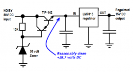
Use a discrete pre-regulator, optimized for low parts count, to drop most of the excess voltage and dissipate most of the heat (Darlington needs a heatsink). Then a proper regulator IC provides low output impedance and good regulation. Simple to explain, simple to understand, difficult to screw up. Forgiving of novice mistakes.
Optionally, substitute the fanciest Hyper Mega Super Regulator circuit on the planet, instead of the plebeian single-chip LM7815.
_
Optionally, substitute the fanciest Hyper Mega Super Regulator circuit on the planet, instead of the plebeian single-chip LM7815.
_
Attachments
Last edited:
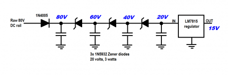
I appreciate the suggestion. I just want to stay away from having zeners in the active current handling part of the vreg circuit. Maybe a few amplified zeners in that arrangement would be worth exploring. I just get nervous about oscillation with a design like this and killing the amp - matched J74s and K170s are not easy to come by these days.Sutherland-style ladder using zener diodes as level shifters. IC voltage regulator at the end for low output impedance and good regulation. Simple to explain, simple to understand, difficult to screw up. Forgiving of novice mistakes.
_
Yeah, that was an option I was looking at. It appears reasonably simple and very effective. Definitely much better than dumping all the voltage and heat across one large resistor into a tiny 1 watt zener.Use a discrete pre-regulator, optimized for low parts count, to drop most of the excess voltage and dissipate most of the heat (Darlington needs a heatsink). Then a proper regulator IC provides low output impedance and good regulation. Simple to explain, simple to understand, difficult to screw up. Forgiving of novice mistakes.
_
Hi guys, I actually recommend that you: Leave it alone! The problems are mostly in the output stage, not the input.
Gee guys, I didn't mean to scare you off! I just wanted to point out that the 'problems' or design tradeoffs in the A21 are mostly in the output stage, its quiescent current, the mos fet complementary driver current, power supply capacity, etc. This design is almost the same as the more expensive JC-5 and even the JC-1 series. It is just MORE: current, output devices, heatsink, power supply and its driver regulation, etc, etc that turns a good amp (that is affordable) into an amp that can drive almost anything, effortlessly. I recommend that you concentrate on what is most important, rather than attack some side 'compromise' like using a simple power resistor/zener combination instead of a full regulator. It might be possible to improve this simple combination, but easiest to just add a parallel resistor to the existing resistors to add an increased amount of current at 15V. Not too much, however, or you will overheat the 15V Zener.
Thank you for chiming in! I appreciate your input and can see what you mean by pointing out the other A21 design compromises, but the reason I was picking on the resistor and zener combo are two fold.Hi guys, I actually recommend that you: Leave it alone! The problems are mostly in the output stage, not the input.
One is getting the heat away from the pcb to not cook it - seen a few of these A21 PCBs get ruined by the resistor frying away at sometimes close to 300 degrees F.
The other main reason is lack of PSRR in the VAS stage. As mentioned, I used separate clean regulated +/- 15V to power the front end and it made a pretty big difference, almost putting the amp in a whole different league of sound in my circumstances, which was driving some current hungry B&W 802s that dip far down in the lower mids. The difference was not so much there with 8 ohm nominal loads.
The regulation of the 15v zener is lousy and lets a ton of crap get through past the front diff, mixed with current modulated components of the output stages pulling on the rails as well as dirty ac power stuff coming through. I wouldn't have believed it would affect the sound so much if I hadn't tried a cleaner source of 15V. Its definitely more audible than one would think. The other thing to replace is the budget low grade filter caps, but thats more of a precaution than anything. I may be surprised though. We'll see.
I found its actually easier to design a separate small toroidal PS with discrete depletion fet CCS for supply and TL431 ref CC shunt to sink half of it away, leaving me with about 250 mA to play with. This should give me a rock solid supply that won't budge when the line voltage goes all over the place. I did a similar VAS supply mod to my el cheapo HCA1500A (as a guinea pig) which also made a significant improvement. I thought that just upgrading the NFB resistor in that amp with a holco did wonders here, but the PS made it sing.
Down here in AZ we have severely polluted ac line power from all the constantly cycling ac compressors. That may be why I'm noticing such big improvement. Its more of a concern here than in other parts of the country that have cleaner ac power.
Well P, welcome to the world of hi-end audIo! Your suggestions are perfectly reasonable, given your poor line power and your concern for the best possible sound from the A21. I might have to mention that there are 2 models (much more expensive) that probably would sound better in your environment that have addressed your complaints. But they are not more expensive for nothing, it takes MORE regulation, bigger power supply, more quiescent current, etc, etc but it DOES make for a better amplifier sonically. Personally, I am using a JC-5 with my Wilson Sasha speakers (2 ohm sometimes) and I earlier realized the the A21 would not do the job, but the JC-5 does pretty well (at least for me with my AC line), and it is stripped down from the JC-1, much as the A21 is stripped down from the JC-5. I was pleasantly surprised that it sounds good enough for me, but it does. The JC-1 is even better in every way, but it costs 6 times as much as your A21, while the JC-5 costs twice as much. Apparently, when the A21 was finalized in Taiwan they went a little too far, but I can't fault their design decisions on paper at least. However, the A21, or the even cheaper A23, do not have my JC recognition on them, BECAUSE they are compromised due to cost considerations. I can't do anything about that with Parasound, but we might be able to make some DIY improvements like you have just done to improve the performance of the A21's out there for those who are willing to put the time and money into doing so. Let's hear other suggestions!
John , about time you showed up..........you senior audio designers sure take their time..... 🙂
prifiguy,
I suggest you trying a capacitance multiplier, as in the schematic (taken from Elliot's page), by adjusting resistor values you can drop some volts followed by the resistor and zener. Ignore the values in the circuit and calculate how much of a drop you need, you will improve your regulation and drop the heat dissipated by the resistor. Adjust the raito of the 220ohm and 1.2kohm resistors attached to base of the pass transistors. In this instance you probably do not a darlington pass transistor.
Jam
@jam Good call on the cap multiplier. Depending on amount of local gain of darlington stage, it can be fairly wide band. I've dabbled with these before but ended up discouraged by the sloppy transient response up past 10k or so including the phase shift as well. IIRC those TIP35/36 are a bit hard to come by these days from reputable vendors.
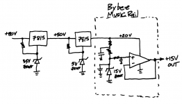
@Mark Johnson those cascading linear 78xx / 79xx could work if the turn on time was identical between them, so the individual regs don't have their safe input ranges exceeded. IIRC the limit is 37v for the standard versions. I've blown up these 3 pin regs before trying to adapt them to higher voltage applications and the problem is during the turn on phase, when the adjust pin cap isn't charged yet and the full delta V is momentarily across the one reg. Leaving out the cap across V adj pin to ground helps but makes the reg output noisier.
@Mark Johnson those cascading linear 78xx / 79xx could work if the turn on time was identical between them, so the individual regs don't have their safe input ranges exceeded. IIRC the limit is 37v for the standard versions. I've blown up these 3 pin regs before trying to adapt them to higher voltage applications and the problem is during the turn on phase, when the adjust pin cap isn't charged yet and the full delta V is momentarily across the one reg. Leaving out the cap across V adj pin to ground helps but makes the reg output noisier.
7815 is a fixed output voltage regulator IC, it doesn't have an "adjust pin". I've had good success using 7815s for HV applications, with judicious application of protection diodes in crucial spots. Some positions want Schottky diodes, others want Zener diodes, others want ordinary rectifier diodes. At least in my experience. It's worth spending some design time trying out unorthodox diode ideas, in large part because 7815's are so cheap and so widely available even during a global supply squeeze.
If you prefer adjustable output voltage regulators like 337/317 rather than fixed output regs, because then you'll get an "adjust pin", consider modifying the Maida bootstrapped cascode to fit your requirements. Lots of people use the Maida circuit in vacuum tube audio amplifiers without incident.
_
Attachments
- Home
- Amplifiers
- Solid State
- Better V-reg for Parasound A21 amp?