Been there, done that... I never found the power supply of the soundcard to be a problem, other than the phantom power. The loop measurements of yours are already very good I think, especially complimented by REW. The ground loop problem when a DUT is inserted better addressed with a floating input rather psu.I will carefully look out for not going higher than this MAX level MagicBus.
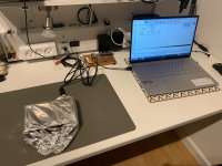
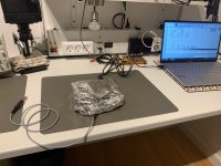
While i'am stock here at home rest of the week, i did try another experiement with batterysupply to the Behringer.
Jesper...
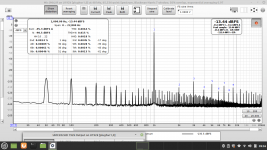
Picture's speak for themself. Batterypower is not better, likely a bit worse in my case.
The measurement's are with same setting's and adjustment's. (I use my Right channel in/out with YashN's mod etc... as i wrote in earlier post)
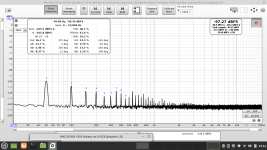
So... this is the best i can archive when measuring an real amp. (cloneamp. at my lab.).
I tried allmost everything regarding lifting GND's, making "star" connection's etc... nomatter what, i seem to stuck with the forrest -noisefloor.
But okay it's better now at least.
I'am looking forward to recieve Alfred's pcb to buildin between R98 / R99 (DAC filter ---> line out) to try that out.
Jesper.
Attachments
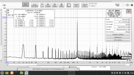
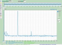
Depends where you're looking.Picture's speak for themself. Batterypower is not better, likely a bit worse in my case.
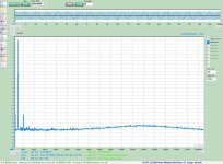
You're better off with the battery to look into details concerning the lower ranges. Compare this portion near the mains harmonics and it's far better on battery.
It's very good you have both options.
Hi Jesper, all,
I had the same problem at my working bench. I found after a lot of experiments that the 100 Hz and multiples are introduced by HF of my Fritz Box, by WLAN (2.4 or 5 GHz) and DECT at 1.9 GHz into the amp. Going to a place in my house far away from any transmitter, this "Lattenzaun" is gone.
I also found that different amps show different levels. The OPA2209 (a very good amp, low noise, low TDH) shows it very strong, the well know NE5532 less, but still there. A TL072 almost nothing. I tested also a TLV9062 from TI (+5V, rail to rail) and the signal is clean. This might be an alternative to the AD8692, Behringer used. (But you cannot buy both right now) Maybe the JFET input show less of this effect. I will do more tests in the next days.
I would recommend to turn off the WLAN, DECT, Mobile etc.
The pictures are made with a small board with gain of +10, OPA2209 and TL072
Please tell me your findings!
Alfred
Attachments


Interesting comparisons, Alfred. Yes, sadly, buying parts right now is complicated. I got burned with import fees in my most recent order from Digikey.ca as the parts came from the US. Had to pay $35 (CAD) of duty on around $125 of parts. At least shipping was free (over CAD 100 it is free).
So no more orders from me until prices get better unless absolutely necessary - I hardly think there will be any need: I can wait things out by using the parts and salvaged parts I have at hand to conduct many experiments. I may not be able to complete a few full builds but I can wait.
So no more orders from me until prices get better unless absolutely necessary - I hardly think there will be any need: I can wait things out by using the parts and salvaged parts I have at hand to conduct many experiments. I may not be able to complete a few full builds but I can wait.
So what may be the source of your 100Hz "Lattenzaun"? Probably some 100Hz sawtooth ripple - originating from full-wave rectification inside your amp. That is where I would look further...Hi Jesper, all,
I had the same problem at my working bench. I found after a lot of experiments that the 100 Hz and multiples are introduced by HF of my Fritz Box, by WLAN (2.4 or 5 GHz) and DECT at 1.9 GHz into the amp. Going to a place in my house far away from any transmitter, this "Lattenzaun" is gone.
I also found that different amps show different levels. The OPA2209 (a very good amp, low noise, low TDH) shows it very strong, the well know NE5532 less, but still there. A TL072 almost nothing. I tested also a TLV9062 from TI (+5V, rail to rail) and the signal is clean. This might be an alternative to the AD8692, Behringer used. (But you cannot buy both right now) Maybe the JFET input show less of this effect. I will do more tests in the next days.
I would recommend to turn off the WLAN, DECT, Mobile etc.
The pictures are made with a small board with gain of +10, OPA2209 and TL072
Please tell me your findings!
Alfred
YashN, i see your'e point regarding the "noise" around mains, also if i look closely as you mention, the noisefloor is a little lower going on battery power.
Alfred, most interessting observation, which i never get a throught... good thing i have one more day at home in quarantine to go offline at house, and with cellphone powered down... hey like in the 80's that is 😎 ... will report back.
bucks bunny, i will try again some other amp's tomorrow including my 300B SE... let's see if cutting everything to offline help's first. - This is most interessting.
Today i tried a bunch of trick's to get rid of the main's + freinds hum/noise, including grounding the hole setup to an heaterpanel, which pipes are going into ground outside... but nothing really did any difference... I also consider to make a shield inside the Behringer to see.
Jesper.
Shielding will help reduce 50Hz noise - but not the 100Hz pattern originating from power supply rectificadtion
Shielding will help reduce 50Hz noise - but not the 100Hz pattern originating from power supply rectificadtionToday i tried a bunch of trick's to get rid of the main's + freinds hum/noise, including grounding the hole setup to an heaterpanel, which pipes are going into ground outside... but nothing really did any difference... I also consider to make a shield inside the Behringer to see.
Jesper.
Hi all,
one thing I forgot to mention. With my test board at gain +10 close to the fritz box, shorted input, I could measure the 100 Hz pattern with my scope. Since triggering was unstable due to the small and noisy signal I switched the scope to line triggering. To my surprise the 100 Hz pattern was not synchronized with "my" line.
The frequency is very close but not the same. I have no idea why! Do I measure the line frequency of somebody else?
The 50, 150 and 250 Hz was clearly introduced by magnetic fields.
Alfred
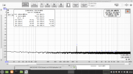
I tried cutting everything off (wifi, router, Philips Hue etc... cellphone etc...) looking at the spectrum at every step.
Unfortunately it didn't matter much in my setup.
So then i tried some alufoil to see if i could shield the EMF/RF whatever.
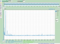
The result's are clear to me i guess?!, when the Behringer is all foiled up, there is no spikes.
When i plugin e.g. the input jack it act as an antenna.
Even if i attach the bare input jack end to my measurement rig i still got the spikes.
This is with no DUT, so it must be the Behringer or something in the air witch give the spikes?
There is also an attachment of the best result i can get, measuring my cloneamp.
Jesper.
Unfortunately it didn't matter much in my setup.
So then i tried some alufoil to see if i could shield the EMF/RF whatever.
The result's are clear to me i guess?!, when the Behringer is all foiled up, there is no spikes.
When i plugin e.g. the input jack it act as an antenna.
Even if i attach the bare input jack end to my measurement rig i still got the spikes.
This is with no DUT, so it must be the Behringer or something in the air witch give the spikes?
There is also an attachment of the best result i can get, measuring my cloneamp.
Jesper.
Attachments

The observation that the spikes are not synched to mains is strange. Does the mains trigger work properly in case of 50hz signal injection? Sometimes I got strange spikes bases around 30Hz caused by XRUNS of my linux sound system.
Full wave rectification does not produce 50Hz noise.Looks like some rectifier noise is entering
Don't forget that mains AC voltage is not just a 50Hz (or 60Hz) fundamental, and the higher the harmonic the easier it is to couple in to your measurement rig.
Hi all,
I did some better pictures of the external filter while I switched off the Fritz Box. Done with the RME at 96 KHz.
Loopback is the RME itself. Then two pictures of the filter in between. The bump of the noise around 24 KHz is the filter.
You can also see it in simulation.
Again the 50, 150 and 250 Hz is hum.
Alfred
Attachments
Nice experiment, and very cool and clean setup you have there.I tried cutting everything off (wifi, router, Philips Hue etc... cellphone etc...) looking at the spectrum at every step.
Unfortunately it didn't matter much in my setup.
So then i tried some alufoil to see if i could shield the EMF/RF whatever.
Morning all here...
First off, thank's to Alfred for being so patient, answering my quistion's.
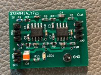
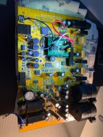
Well i build Alfred's 4. order lowpass 21kHZ filter.
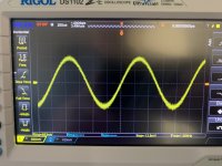
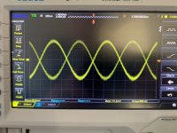
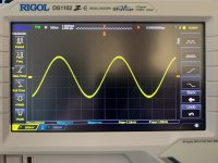
To be very honest, it took me a couple of day's figuring out the purpose of this 4.order lowpass filter, but eventually i figured out, that it is an DAC output filter, better than the one stock with the Behringer. (The sinewaves clearly show's this / 3 pictures)
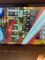
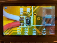
I was fiddeling around, and finally i installed the filter on one channel only. The filter is put in between where resistor R98 used to be. (Pictures 🙂 also)
So this giving me the possibility to compare. (With & without Alfred's filter)
So i now have the following mod's installed in my Behringer ::
Channel B (Right side) :
Input B ---> preamp bypass (YashN's mod) ---> // ---> Output B (Alfred's 4.order lowpass 21kHZ filter / picture of soundcard calibration shows this)
I also kindoff did an GND mod myself, connecting a GND pad on the pcb to the backplate / chassis of the Behringer...
More to come... stay tuned here 😎
First off, thank's to Alfred for being so patient, answering my quistion's.
Well i build Alfred's 4. order lowpass 21kHZ filter.
To be very honest, it took me a couple of day's figuring out the purpose of this 4.order lowpass filter, but eventually i figured out, that it is an DAC output filter, better than the one stock with the Behringer. (The sinewaves clearly show's this / 3 pictures)
I was fiddeling around, and finally i installed the filter on one channel only. The filter is put in between where resistor R98 used to be. (Pictures 🙂 also)
So this giving me the possibility to compare. (With & without Alfred's filter)
So i now have the following mod's installed in my Behringer ::
Channel B (Right side) :
Input B ---> preamp bypass (YashN's mod) ---> // ---> Output B (Alfred's 4.order lowpass 21kHZ filter / picture of soundcard calibration shows this)
I also kindoff did an GND mod myself, connecting a GND pad on the pcb to the backplate / chassis of the Behringer...
More to come... stay tuned here 😎
Attachments
Last edited:
Probing the output of my EMU sound cards with a scope showed ugly high frequency noise as well. So I did some tests with low-pass filtering to smooth the sine waves which apparently worked. But the measured numbers of THD+N in the audio band did not change at all. What we see on the scope is outband noise, not nice on the scope - but beyond audio relevance. The same applies to class d-amps. The rf-residual after filter gives a smeared sine-wave which contributes to noise far above the audio band. We do not "see" music on a scope with a bandwidth of 100MHz or more, the bandwidth limited soundcard measurements are a far better representation of what we hear. For my lab applications only I have built a latFET class-B-amp.
Btw, a 21kHz filter is no bad option at all but must be bypassed if you want to extend measurements beyond 20kHz with higher sample rates.
Btw, a 21kHz filter is no bad option at all but must be bypassed if you want to extend measurements beyond 20kHz with higher sample rates.
- Home
- Design & Build
- Equipment & Tools
- Behringer UMC 202HD for measurements