You may want to have a cheap pair of speakers (or a 4 to 8 ohm dummy load) hooked up to the outputs when you do the reset. Someone on this forum recommended holding the momentary reset switch as you power it on https://www.diyaudio.com/community/threads/3e-audio-board-reset.350841/ as opposed to after the amp is powered up. I can't say which is the appropriate manner to do a reset. Good luck
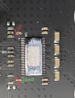
Thank you turion64 for your help so far.I'm not sure why "C" is not showing any voltage. I believe the voltages measured at "B" & "C" are generated by a regulator circuitry internal to the chip while "A" & "D or E" have to be supplied external to the chip. I'll have to read the 3255 datasheet in more depth. Let's try something simple. If you haven't tried a RESET of the amp let's try that. All you should need is a SPST momentary push button between the reset pin and ground pins on the board (if you've got steady hands you could just use a piece of wire as a jumper). The board must be powered up when doing the reset.
I had already tried resetting the amp by grounding the RESET pins. I did it once again by holding the RESET ping while powering up the board before retaking the measures. The measures show the same as read previously and there is still no sound.
Also, C - GND is actually not 0 but more like ~5mV.
Last edited:
The TI datasheet says the reset + ground only has to be held for 1/4 sec past power on and then disconnect the reset + gnd connection.. This is what you did, correct? If yes, try again anyway. If still don't get approx 7vdc out of "C" it sounds like the chips internal regulator for its analog circuitry (AVDD) is bad.
Yes, did exactly as you described for the RESET pin. Remeasured again, still ~5mV out of C.The TI datasheet says the reset + ground only has to be held for 1/4 sec past power on and then disconnect the reset + gnd connection.. This is what you did, correct? If yes, try again anyway. If still don't get approx 7vdc out of "C" it sounds like the chips internal regulator for its analog circuitry (AVDD) is bad.
At this point, unless any of the other forum members have any insights, you may to to contemplate replacing the 3255 chip, if you have the ability to do so. I guess you can try contacting 3e Audio's technical/customer service via email but I heard frustrating stories from other folks. Sorry we couldn't get the amp going for you.
Pete
Pete
If you just wanted to see (just because ) you could measure "E & F" points (GVDD AB/CD) to make sure they are receiving ~12V as well. I think I marked the ground correctly this time.
Attachments
3eAudio is a member on here, and was present last Friday. It may be worth DMing him?
https://www.diyaudio.com/community/members/3eaudio.318050/#latest-activity
https://www.diyaudio.com/community/members/3eaudio.318050/#latest-activity
Just because, D and E are correctly receiving 12V.
It is a brand new board that I bought last month on Audiophonics. It should come with 2-year warranty. I am filling in an RMA request.
It is a brand new board that I bought last month on Audiophonics. It should come with 2-year warranty. I am filling in an RMA request.
... and so you shouldJust because, D and E are correctly receiving 12V.
It is a brand new board that I bought last month on Audiophonics. It should come with 2-year warranty. I am filling in an RMA request.
Pete
I received a new board back from RMA. It now works as it should, the sound is fantastic!
There are a couple of cracking noises coming out of the speakers when the amp powers up, I was wondering if there is something that can be done to avoid them and how you guys deal with it?
There are a couple of cracking noises coming out of the speakers when the amp powers up, I was wondering if there is something that can be done to avoid them and how you guys deal with it?
You could put a speaker delay circuit after the amp output if you want. There are Many to choose from in the DIY world that range from simple relay circuits to ones with both delay circuitry + DC protection circuitry.I received a new board back from RMA. It now works as it should, the sound is fantastic!
There are a couple of cracking noises coming out of the speakers when the amp powers up, I was wondering if there is something that can be done to avoid them and how you guys deal with it?
The one's that quickly come to mind are:
https://diyaudiostore.com/collectio...speaker-turn-on-delay-and-dc-protector-boards
https://www.jlelectronicsph.com/product/blank-pcb-for-stereo-speaker-protect
Another is designed by Pete Millet and is available through eBay.
Cheers, Pete
You need to look for speaker protection for Class D amplifiers that interrupt both the + and - line. With classic protections, only + line is interrupted, - line is common, which is generally not allowed for amplifiers in class D.You could put a speaker delay circuit after the amp output if you want.
I'm interested to buy your amp. the tpa3255 with onboard psu. is it still available?Made a new PSU.
LLC, controller L6599, tranformer from Wurth Electronic.
You might as well just send me the money instead...I'm interested to buy your amp. the tpa3255 with onboard psu. is it still available?
Check this thread to see the unhappy customers:
Throw Your Money Away
so what brand of of tpa3255 you will suggest then?You might as well just send me the money instead...
Check this thread to see the unhappy customers:
Throw Your Money Away
I would choose out of the following:
3e-Audio https://www.audiophonics.fr/en/ampl...4690.html?search_query=tpa3255&fast_search=fs
JLesterP https://www.jlelectronicsph.com/products
XRK971 https://www.diyaudio.com/community/threads/tpa3255-reference-design-class-d-amp-gb.340880/
XRK971 only has bare boards/pcbs at the moment, so if I was to buy now, I'd probably go with JLesterP, who is very active on this forum, and there are various threads on builds using his boards.

How do you like the A09? I’m looking for a 4 channel amp to power my open baffle 3way project. Mid and tweeter with a analog XO and bass driver integrated with active XO.Danny (on this forum) has experience of this board !! The first time it was plugged in the 12volt regulator burnt out. Manufacturer only used 40volt regulator components on a 48 volt board. Also inductor values in the Power Supply appear to be wrong and hence overloading the regulator !
So if you buy this board expect to do some reworking before you attach to Power !!
Danny has it working now after replacing some components so can probably tell us what it sounds like.
On the Aiyima A09 TPA3255 unit, I have this same unit without the Anti-Pop circuit and yes it makes a big noise when turning on and off with the front switch ! If you turn the power off and on to the power supply there is almost no noise. The latest release of the PCB In this model now appears to include the Anti-Pop circuit and is identical to the Tilear Aiyima A04 TPA3251 model.
Mini dsp 2x4 sent to A09 and then different drivers plus sub.
are there reviews include measurement diagrams in "Stereophile" about power amplifier models where the TPA3255 from TI is in use ?
Hi,are there reviews include measurement diagrams in "Stereophile" about power amplifier models where the TPA3255 from TI is in use ?
Apart from audiosciencereview, i have not seen any TPA3255 reviews.
I have seen Hifi News test Infineon based class D amplifiers, and they get decent subjective reviews :
https://www.hifinews.com/content/agd-gran-vivace-monoblock-amplifier-lab-reporthttps://www.hifinews.com/content/ta-pa-1100-e-integrated-ampdac-lab-reportIt would be nice to see one of the cheap TPA3255 amplifiers reviewed. If the Infineon IRS2092 or other driver/modulation IC is acceptable as a solution, then the TPA3255 should be too.
Regards,
Shadders.
- Home
- Amplifiers
- Class D
- TPA3255 - all about DIY, Discussion, Design etc