Thank you all for providing your input.

There isn't something as trivial as an on/off switch or jumper on the amplifier board, is it?
Normally you just connect the power supply, connect inputs and outputs and hear music?
Tried that, no luck either. Tried switching the se-diff as well.Try reversing the input connectors...rotate 180
degrees. 🤔
These ones you mean. They are the stock ones.Are there any opamps in their respective sockets?
The mains switch was off while fiddling with the cables on the first pictures. See on the above picture the power led light does switch on.Sure you have power in?Don't see the power led light.
Not at all, not even a single noise from the speakers when turning main power on/off or fiddling with the input connectors. No noise from the board neither.Did you ever have the 3e playing at all?
There isn't something as trivial as an on/off switch or jumper on the amplifier board, is it?
Normally you just connect the power supply, connect inputs and outputs and hear music?
Could it be an grounding issue?Thank you all for providing your input.
Tried that, no luck either. Tried switching the se-diff as well.
These ones you mean. They are the stock ones.
View attachment 1018263
The mains switch was off while fiddling with the cables on the first pictures. See on the above picture the power led light does switch on.
Not at all, not even a single noise from the speakers when turning main power on/off or fiddling with the input connectors. No noise from the board neither.
There isn't something as trivial as an on/off switch or jumper on the amplifier board, is it?
Normally you just connect the power supply, connect inputs and outputs and hear music?
I have my board mounted with nylon distances just to be sure it not grounding to the amp, just floating ground.
Also the RCA connectors have no ground to metal case.
Not that I remember ...it was plug-n-playThank you all for providing your input.
There isn't something as trivial as an on/off switch or jumper on the amplifier board, is it?
Yup.Normally you just connect the power supply, connect inputs and outputs and hear music?
Take the board out and take a good picture of the under side. Let's see if some bad solder joint can be spotted. Then take the heatsink off and see if anything glares out at you.
I removed the board from the chassis and unscrewed the metallic risers as Solve was suggesting. The board is now literally floating. Still no luck unfortunately, absolutely no sound coming out from the board.Any luck teubell?
I flipped the board around as you suggested but I don't really see anything shocking here.
Everything seem to look good underneath the heatsink doesn't it
I am starting to think that the board might be defective. What do you think? Anything else I could be trying?
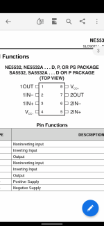
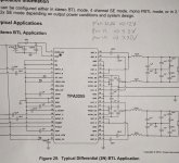
teubell, do you have a volt-ohm meter to check voltages going into the opamps (pins 4 &8) & into the 3255 (pin 2 & 12or13) chip? Be very careful on the 3255 chip not to short other pins. Someone check my 3255 pin choices..
Last edited:
use the out side of the cap (for pin 2) and either pin 12 or 13 for GND. Only run the power briefly as you have no heatsink on the chip. I'll measure my voltages on this chip later today and tell you what I get. Do the opamps first.

No. 4 is correct. 8 is the other end of that side
Look at a 5532 data sheetNo. 4 is correct. 8 is the other end of that side
Attachments
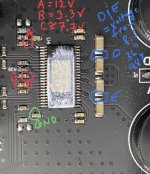
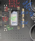
Ok, I tested voltages on another 3255 amp (w/o the heatsink on) and highlight testing points that should be on the 3e board. I was using a 48V PS to powered the board. If the 3255 chip is working it should get it should get very warm to the touch (I tested with no signal in and no load on the speaker outputs). If it doesn't get really warm it may be dead.
Pete
Pete
Attachments
We might have something here, below are my measure readings according to your notes:
A - GND: 0V
B - GND: -12V
C - GND: -12V
D - GND: 24V
E - GND: 24V
My power supply is 36V. Measured between PVDD and GND on the board we actually read 36V.
Everything was measured with all inputs and outputs disconnected.
A - GND: 0V
B - GND: -12V
C - GND: -12V
D - GND: 24V
E - GND: 24V
My power supply is 36V. Measured between PVDD and GND on the board we actually read 36V.
Everything was measured with all inputs and outputs disconnected.
Ok, let me actually measure my 3e audio board's voltages just as a check. I'll check backwards and see where the 12V source is soldered on the board and where it's possible to check it with normal probes. This will a day or two. But, using GND#2 this time (as my as the capacitor coming off pin #22 is oriented differently) check for which side of the cap (off pin 22) is going to ground. With the power off, use your continuity setting on your meter and check for continuity between pins 12&13 and both sides of the capacitor (original GND in green). Whichever side of the cap gives you a signal with pins 12&13 use that side as ground and remeasure all the other points against it. The alternative is just to use GND#2 and re-do all your voltage measurements. I was just trying to keep you away from the 3255 chip with power flowing in. The original GND may have been the wrong side of the cap. Apologies
Attachments
Last edited:
Ok, let me actually measure my 3e audio board's voltages just as a check. I'll check backwards and see where the 12V source is soldered on the board and where it's possible to check it with normal probes. This will a day or two. But, using GND#2 this time (as my as the capacitor coming off pin #22 is oriented differently) check for which side of the cap (off pin 22) is going to ground. With the power off, use your continuity setting on your meter and check for continuity between pins 12&13 and both sides of the capacitor (original GND in green). Whichever side of the cap gives you a signal with pins 12&13 use that side as ground and remeasure all the other points against it. The alternative is just to use GND#2 and re-do all your voltage measurements. I was just trying to keep you away from the 3255 chip with power flowing in. The original GND may have been the wrong side of the cap. Apologies
The continuity measure shows indeed that GND #2 and actually the other end of the cap off pin 22 are connected.
Using the other end of the cap as GND the measures now show:
A - GND: 12V
B - GND: 3.3V
C - GND: 0V
D - GND: 36V
E - GND: 36V
I'm not sure why "C" is not showing any voltage. I believe the voltages measured at "B" & "C" are generated by a regulator circuitry internal to the chip while "A" & "D or E" have to be supplied external to the chip. I'll have to read the 3255 datasheet in more depth. Let's try something simple. If you haven't tried a RESET of the amp let's try that. All you should need is a SPST momentary push button between the reset pin and ground pins on the board (if you've got steady hands you could just use a piece of wire as a jumper). The board must be powered up when doing the reset.
- Home
- Amplifiers
- Class D
- TPA3255 - all about DIY, Discussion, Design etc


