Indeed, your soundcard now seems to work nice! How do you connect the DUT to it?
I have two Phono jacks + cables with breadboard leads on the other ends. Works well so far, but I think even this can be improved upon.
Most impressive...
I'am looking forward to see how you have done this.
I only did two mods: mine and the disabling of the DC Booster circuit.
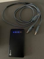
The DUT is a unity-gain buffer powered by batteries as a first non-loopback test.
Tested conductivity/continuity:
Are you sure this is an EMI coating?
- The back panel is metal
- The main box is metal, not plastic, but with paint
- The front panel is plastic
- The back panel's coating doesn't conduct
- There is no provision for contacting the grounding tab to the back panel because of the coating
- There is no provision for the back panel making proper contact with the main box (coating + paint)
Are you sure this is an EMI coating?
The box is aluminum, correct! I was fooled by the plastic front panel. I can't tell much about the coating as this was suggested by other members. The rear panel is bare metal from inside and I can verify continuity with pcb ground in mine. Perhaps things have changed in the production meanwhile?
Hey here guy's...
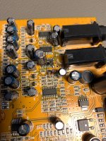
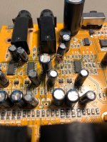
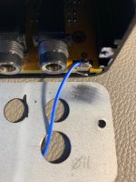
So finally i got around doing YashN's mod + scratching/cutting the pcb-trace to the phantom-power + making better connection to Behringer chassis.
With thoose 3 things i get good results now.
Connection between R out ---> R in is plain MONO jack.
I tried to calibrate the soundcard in REW, but i'am not sure i got it right, will do some more experiment's ofcause.
Thanks all for getting here now 😎
EDIT :: There are good connection between potmeters, backplate, metal parts on chassis now!
Jesper.
Attachments
Looking good.
Note that there is really no need to cut any trace. The removal of inductor L4 achieves the same thing as suggested by Alfred.
I would also scratch the whole internal periphery of the backplate, the area around the screws in the back plate, and scratch the black paint off the very edge at the back of the main box for additional shielding.
The front panel remains a liability though. Additionally, with the new grounding lug and screw you installed, you want to ensure that the area just underneath the lug is free of black paint.
This new lug and screw isn't really necessary IMO: you can improve the shielding as described above and ensure the little tabs on the grounding pads touch the areas you scratched. There may be a need to install a piece of cardboard in there between the pads and the tabs make good contact to the back plate.
I wonder if we can remove the inductors at the inputs and outputs.
What do you think these are good for?I wonder if we can remove the inductors at the inputs and outputs.
Hello,
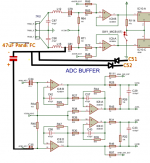
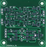
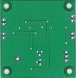
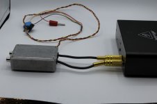
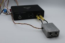
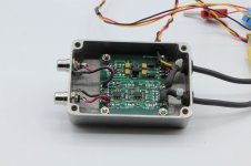
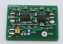
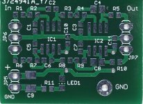
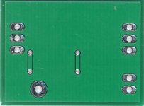
in the meantime I received the filter PCBs, loaded and tested them. The external one is in an alu box from Hammond. The small one will be mounted in the UMC. R98 and R99 will be removed and the filter connected in between. See photos and plots. The filter is a 4. order Tschebyscheff low pass with 0.1 dB ripple in the pass band and 21 KHz corner frequency (But you can use any low pass filter). If anyone is interested in some PCB (Blank Boards), just let me know. (alfred_rosenkraenzer@gmx.de). By the way, my web page: www.alfredrosenkraenzer.de
Measurements are done with the RME interface at 192 KHz.
Attachments
-
 Ext-Filter1.jpg70.4 KB · Views: 149
 -
 Ext-Filter2.jpg31.5 KB · Views: 127
 -
 IMG_0594r.jpg96.3 KB · Views: 141
 -
 IMG_0595r.jpg77.4 KB · Views: 151
 -
 IMG_0596r.jpg108.4 KB · Views: 169
 -
 IMG_0600r.jpg123.2 KB · Views: 168
 -
 Int-Filter1.jpg28.7 KB · Views: 147
 -
 Int-Filter2.jpg13.6 KB · Views: 139
 -
 Tsch-0p1-21KHz-4O-Freq1.jpg141.2 KB · Views: 158
 -
 Tsch-0p1-21KHz-4O-Freq2.jpg122.9 KB · Views: 158
 -
 Tsch-0p1-21KHz-4O-Spec.jpg212.1 KB · Views: 154
Nice work! I assume it works on +/-12V or something? Is it possible to post frequency response at 192kHz and THD+N% at 48kHz please?
The internal filter PCB runs on the internal analog power supply of the UMC (4.5 V). You need an amplifier like the AD8692 used by Behringer.
The external uses +-15 V with +-12V regulators on the PCB. Here you can use NE5532 and many others.
The frequency response measurement of the pure filter board (not with the UMC) was made with my RME interface at 192 KHz.
The spectrum also. There will be no difference using 48 KHz for the spectrum.
Please specify your question. Do you want to see the Spectrum of the UMC generator with the filter measured with the RME?
Ok, it's clear now, thanks! Yes, I was thinking for a UMC plus the filter THD+N% @48kHz for reference.
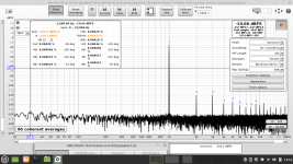
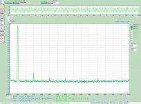
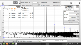
Here are some pictures. The .png files are made with a RF spectrum analyzer up to 3 MHz. The .jpg with the RME. Please note that there is noise at the higher end of the RME even without signal. The names of the pictures tells you what is what.
Attachments
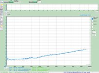
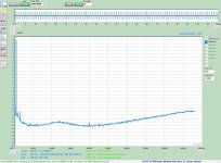


Thank you very much! It does great job with the ultrasonic images but seems to add a bit in the audio band. Do you think this depends on the opamp used?
I would like to see this also.Ok, it's clear now, thanks! Yes, I was thinking for a UMC plus the filter THD+N% @48kHz for reference.
Jesper.
Hello,
in the meantime I received the filter PCBs, loaded and tested them. Measurements are done with the RME interface at 192 KHz.
Very nice, Alfred. Thanks for sharing.
The new graphs do show the removal of the noise-shaping related bumps as I saw them too.
This Behringer interface, with a little work, can be an excellent basis for audio measurements.
This Behringer interface, with a little work, can be an excellent basis for audio measurements.
YashN (Or anyone)...
As i did the mod, bypassing the preamp, how much voltage can the Behringer accept on this input (Right channel only for now).
Jesper.
As i did the mod, bypassing the preamp, how much voltage can the Behringer accept on this input (Right channel only for now).
Jesper.
Usb 5V goes down to 4,7V after some filtering so 2,35V is the rail voltage to the opamps and that will be the absolute max peak input voltage. Better keep it lower.
I will carefully look out for not going higher than this MAX level MagicBus.
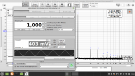
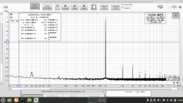
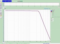
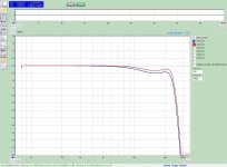
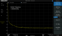
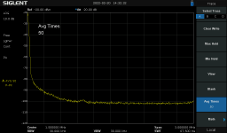
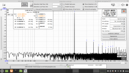
While i'am stock here at home rest of the week, i did try another experiement with batterysupply to the Behringer.
Jesper...
Picture's speak for themself. Batterypower is not better, likely a bit worse in my case.
The measurement's are with same setting's and adjustment's. (I use my Right channel in/out with YashN's mod etc... as i wrote in earlier post)
Attachments
- Home
- Design & Build
- Equipment & Tools
- Behringer UMC 202HD for measurements