Please check the following: in bobun's schematics, the polarities of Al. Electrolytic caps C85 & C82 at inputs are the reverse of what they are on the PCB. It must be the same for the other input.
Bypassed the preamp. Success!

Right Channel only. My initial mod for the Left Channel had a flaw I didn't test for: one of the diodes wasn't soldered properly, so believe one op amp went kaput. Reused the existing XLR/TRS jack.
It's fine, I can do a lot of things now with just that one channel.
A little comparison with before (and just by adjusting settings in the software, we can do even better than the above too):

The board with mods:

Right Channel only. My initial mod for the Left Channel had a flaw I didn't test for: one of the diodes wasn't soldered properly, so believe one op amp went kaput. Reused the existing XLR/TRS jack.
It's fine, I can do a lot of things now with just that one channel.
A little comparison with before (and just by adjusting settings in the software, we can do even better than the above too):
The board with mods:
Last edited:
Thanks to Bobun for the schematics, Remedy and that Polish forum modification link, Alfred, and to you.
Results will be even better if proper shielding is made for the board. What you see above is still the board outside the box.
Results will be even better if proper shielding is made for the board. What you see above is still the board outside the box.
Congarts for the persistence! You have reached a practical mod limit. Some kind of a balance.
Modding the interface more will improve the things further of course, but with diminishing results.
Modding the interface more will improve the things further of course, but with diminishing results.
Thanks Remedy, I agree, it's quite good currently, so I can benefit from putting to measuring use now, putting it back in the box with improved shielding.
Will work on making some connections for breadboards as well tomorrow.
Will work on making some connections for breadboards as well tomorrow.
I noticed something: the front panel is a plastic affair, and it is also screwed in, except there is a glued faceplate with labels on it, obscuring the screws. There is a possibility of hacking this to make a full Faraday cage around the board.
The box is plastic but it has been treated with an anti-EMI coating. You should observe some improvement if you put the pcb back in. Of course, more shielding wouldn't hurt.
YashN.
Could you share the mod you did here? I cant seem to find it nowhere in this thread?
Rgds; Jesper
Could you share the mod you did here? I cant seem to find it nowhere in this thread?
Rgds; Jesper
You're right, Jesper: it's my own spin on a useful mod in the simplest way possible. This can be reversed easily enough: remove mods, then put back the original caps. No relays, no switch, no drilling, no additional switched jack, no trace cutting, no PCB, no differential.Could you share the mod you did here? I cant seem to find it nowhere in this thread?
Here, I am not too concerned about switching the original circuit on and off.
It's for single-ended measurements only.
Requirements:
- One Cap. Either re-use C35 or use a new Cap of your choice
- Two small-signal diodes
- Thin wire
For the Right Channel, and orientation as my board in the pic above:
- Remove C81
- Remove C35. Keep both caps in a safe place for reversal if ever necessary
- New Cap +ve goes into C81 -ve pad
- New Cap -ve goes into C35 -ve pad via thin wire
- Diode 1 goes from C35 -ve pad to bottom of C52 (C52 is the small SMD Cap on the left, diode black marking is oriented down on the picture)
- Diode 2 goes from bottom of C51 to C35 -ve pad (C51 is the larger SMD Cap on the right, diode black marking is oriented up in the picture)
- Tip: solder the diodes by the end pointing towards the C35 -ve pad first, then the other end to the SMD caps. Pre-cut and pre-bend the leads before soldering
- After soldering, do a continuity test to ensure that both diodes are well soldered, or even nudge them a little with a plastic tool to make sure they're staying put. Had I done this, my Left Channel would still be working as I would have caught the faulty soldering in time.
Last edited:
Hey thank's ...You're right, Jesper: it's my own spin on a useful mod in the simplest way possible. This can be reversed easily enough: remove mods, then put back the original caps. No relays, no switch, no drilling, no additional switched jack, no trace cutting, no PCB, no differential.
Here, I am not too concerned about switching the original circuit on and off.
It's for single-ended measurements only.
Requirements:
Mod Procedure:
- One Cap. Either re-use C35 or use a new Cap of your choice
- Two small-signal diodes
- Thin wire
For the Right Channel, and orientation as my board in the pic above:
NB:
- Remove C81
- Remove C35. Keep both caps in a safe place for reversal if ever necessary
- New Cap +ve goes into C81 -ve pad
- New Cap -ve goes into C35 -ve pad via thin wire
- Diode 1 goes from C35 -ve pad to bottom of C52 (C52 is the small SMD Cap on the left, diode black marking is oriented down on the picture)
- Diode 2 goes from bottom of C51 to C35 -ve pad (C51 is the larger SMD Cap on the right, diode black marking is oriented up in the picture)
Use a mono cable for the loopback test and then for measurements. Plug it into the existing XLR/TRS jack.
- Tip: solder the diodes by the end pointing towards the C35 -ve pad first, then the other end to the SMD caps. Pre-cut and pre-bend the leads before soldering
- After soldering, do a continuity test to ensure that both diodes are well soldered, or even nudge them a little with a plastic tool to make sure they're staying put. Had I done this, my Left Channel would still be working as I would have caught the faulty soldering in time.
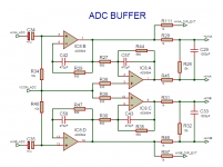
I'am trying to understand the mod, but C51,C52 are not on the schematic. (I did not look at the pcb by now)
I will proberly take a look later today on my pcb.
Jesper.
Hey thank's ...
I'am trying to understand the mod, but C51,C52 are not on the schematic. (I did not look at the pcb by now)
I will proberly take a look later today on my pcb.
You're welcome.
Just look at my pic of the board where the diode legs get soldered. Zoom in if necessary. You'll see the labels on your PCB as well.
These are PSU-related caps. I don't think bobun traced these, but his schematics are still very useful with some caveats.
Yep... okay i then better understand why i could not find them.You're welcome.
Just look at my pic of the board where the diode legs get soldered. Zoom in if necessary. You'll see the labels on your PCB as well.
These are PSU-related caps. I don't think bobun traced these, but his schematics are still very useful with some caveats.
I allready did the "Direct in" mod https://www.diyaudio.com/community/threads/behringer-umc-202hd-for-measurements.341309/post-6898991, where i removed C34 & C35, letting them be bypassed when inserting into the extra TRS jack connector i drilled on the back.
Is this mod more or less the same ? Except that with your's we still have the coil L15 and the capacitor C90 in your's line in connection?
Jesper.
Attachments
The differences are described in my post.I allready did the "Direct in" mod https://www.diyaudio.com/community/threads/behringer-umc-202hd-for-measurements.341309/post-6898991, where i removed C34 & C35, letting them be bypassed when inserting into the extra TRS jack connector i drilled on the back.
Is this mod more or less the same ? Except that with your's we still have the coil L15 and the capacitor C90 in your's line in connection?
First tests on a rapidly breadboarded circuit today with the modified Behringer UMC202HD. Works super well indeed.
Digging deep:

Glad I did this.
Digging deep:
Glad I did this.
The box is plastic but it has been treated with an anti-EMI coating. You should observe some improvement if you put the pcb back in. Of course, more shielding wouldn't hurt.
You're right, I noticed the coating. Maybe I'm wrong but it seems to me the back panel is the sole metal piece.
Additionally, I wonder if coating everything is the best practice here or if the PCB itself should be linked to the metal of the box itself.
Worth a try, IMO.
Most impressive...
I'am looking forward to see how you have done this.
Will wait for it before i will redo mine.
Rgds; Jesper.
The rear panel is grounded to the pcb through two big pads at the corners.You're right, I noticed the coating. Maybe I'm wrong but it seems to me the back panel is the sole metal piece.
Additionally, I wonder if coating everything is the best practice here or if the PCB itself should be linked to the metal of the box itself.
Worth a try, IMO.
Indeed, your soundcard now seems to work nice! How do you connect the DUT to it?
The rear panel is completely coated, do the pads actually contact the metal? I haven't checked the coating for continuity.
Another thing: if there is indeed continuity, there are tabs which are supposed to do the contact with the back panel. Ensure you haven't pushed in the tabs while getting the pcb out and manipulating it or there is no chance of any contact at all.
Another thing: if there is indeed continuity, there are tabs which are supposed to do the contact with the back panel. Ensure you haven't pushed in the tabs while getting the pcb out and manipulating it or there is no chance of any contact at all.
- Home
- Design & Build
- Equipment & Tools
- Behringer UMC 202HD for measurements