Hello tombo56,
this is a great project! Thanks!
I have ordered some pcbs and parts. I will test it as input - buffer in my 50W-SE-Schade-amp.
Cheers
Dirk 😎
this is a great project! Thanks!
I have ordered some pcbs and parts. I will test it as input - buffer in my 50W-SE-Schade-amp.
Cheers
Dirk 😎
Lookin’ good Wg45!
“LUDEF Powered In 30”
Almost sounds like the title should be in the Fast and Furious series, Hehe!
I varied input voltage from +/-20v to +/-45v to the buffer boards with a bench supply and voltage at the OPA828 was steady at -13.79v and +13.80V.
My plan is to try them in my Pass M2 clone. When I built the M2, I installed the JFET’s and P2 trimpot in sockets for future upgrades. Signal output/power input for the buffer will use these positions. With the JFET’s and trimpot removed power can be taken from the vacated Drain sockets to feed buffer. Input signal will use the existing Molex KK header and feed C4 by installing a jumper between J1 Gate and P2 #2 position socket.
Should I remove the M2 input components R1, R2 and C0 since the buffer has similar input components already installed, no need for redundant parts, correct?
Attachments
It is last 30 minutes that counts.Now I just need to build my LuDef in 30 minutes or less.....

Easiest way would be to remove R1 and connect IN-1 with transformer PIN1 or C4 negative pin. As buffer has less than 1 mV DC offset (usually 100 uV), C4 is not required. All other parts can be left in place as removing JFETs and R1 leaves them unconnected or “floating”.With the JFET’s and trimpot removed power can be taken from the vacated Drain sockets to feed buffer. Input signal will use the existing Molex KK header and feed C4 by installing a jumper between J1 Gate and P2 #2 position socket.
Should I remove the M2 input components R1, R2 and C0 since the buffer has similar input components already installed, no need for redundant parts, correct?
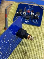
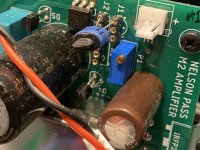
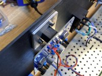
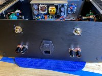
TomboBuffer Pass M2 clone conversion completed. I fabbed up a pair of aluminum adapter plates to mount the buffers in the rear panel holes that were originally cut for the standard Neutrik panel mount connectors.
Tombo, your suggestion of bypassing the M2 input components with a link from input to the neg. side of C4 made me rethink my original plan and gave me the final push to remove C4 altogether. I decided to pull the amp boards from the heatsinks, remove C4 and R1, connect a wire between Molex input header pin and C4 neg pad. Took Pos/Neg power directly from the psu cap bank (no ground wire, ground is provided by signal output GND).
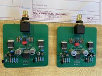
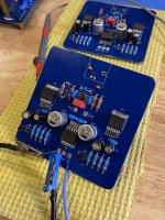
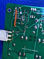
The buffer boards are built as per the schematic with 330R installed at R12. I installed one buffer to compare volume against the channel with JFET’s still installed and could not tell a volume difference between channels with this gain setting.
Drama free power up and dead silent background with music paused. Now it’s a matter if listening time to get a feel if the M2 has changed in any way.
Very nice project Tombo, thank you for sharing 🙂
Tombo, your suggestion of bypassing the M2 input components with a link from input to the neg. side of C4 made me rethink my original plan and gave me the final push to remove C4 altogether. I decided to pull the amp boards from the heatsinks, remove C4 and R1, connect a wire between Molex input header pin and C4 neg pad. Took Pos/Neg power directly from the psu cap bank (no ground wire, ground is provided by signal output GND).
The buffer boards are built as per the schematic with 330R installed at R12. I installed one buffer to compare volume against the channel with JFET’s still installed and could not tell a volume difference between channels with this gain setting.
Drama free power up and dead silent background with music paused. Now it’s a matter if listening time to get a feel if the M2 has changed in any way.
Very nice project Tombo, thank you for sharing 🙂
Attachments
-
 80DB9C1B-11B3-4B12-B673-D5C900AF9550.jpeg530 KB · Views: 173
 -
 06177619-3E37-441C-99C6-E47B7F45E654.jpeg381.7 KB · Views: 203
 -
 3CD4B55D-1FC0-4514-914F-4BFFDAA32D44.jpeg544.8 KB · Views: 190
 -
 6845BE08-D304-4A67-906B-6615D1549091.jpeg377.5 KB · Views: 188
 -
 A6E83681-9DB8-4F5B-8135-97A1AABFEC6E.jpeg533.9 KB · Views: 196
 -
 1E3264D9-CC5E-423F-BFBC-4EB5982A88F5.jpeg329.6 KB · Views: 197
Very Nice, Vunce! I'm interested to hear your impressions.
I think it's going to be a bit before I put my pair to use.
I think it's going to be a bit before I put my pair to use.

Fantastic job with utmost attention to detail.Drama free power up and dead silent background with music paused. Now it’s a matter if listening time to get a feel if the M2 has changed in any way.

I see the same signature on complete amplifier build.
Default buffer gain is just 2.5 dB, Hard to notice in workshop conditions.
Buffer needs 1 day burn-in to sound best. At least, that was my impression. I would avoid discussion weather burn-in exists, is it chemistry settling in electrolytic capacitors or psycho-acoustic brain adaptation or something else. It doesn’t matter. Though, I experience this effect only with complex equipment, never with cables or wires.
There will be difference in sound. You may be in for some surprises with soundstage. Nothing dramatic though. This buffer won’t create something that doesn’t exist in source sound (except very low added distortion).
For instance, deciding to switch transformer drive back and forth between default buffer and this one, while listening to the same song, here is illustration of one difference. It happened that I was listening to Cowboy junkies Misguided angel. At 1:30 and 3:00 marks, male vocal joins female leading vocal. It is subtle and well blended. With default buffer, male vocal was roughly on the same soundstage spot as female vocal. With new buffer, male vocal was vocally more distinguished from female vocal and was moved to the right.
This only confirms that on my system there was a difference. Every system is a mix of very different components, so exactly the same may not happen.
Last edited:
Buffer can be supplied from lower voltage supplies, down to +- 12V. For 15 V it is enough to change R1,R2,R7,R8 to 4K7.Wow, way cool!
Question tho- how would you downscale the regulator chips for lower input V (+-15v) and for lower cost?
OPA551, employed as super regulator, is essential for using this with power amplifiers. For preamplifier or headphone amplifier use, on condition that existing power supply is of very good quality, they can be omitted, and supply can be attached directly at C13/C14, honoring that supply voltage should not exceed +- 18 V maximum and +- 4 V minimum.
Hello Tombo,
Since I haven't completed my LuDef build, where would I add the input buffer connections to the LuDef schematic?
If I understand correctly, it will replace the 2SK2145 Jfets. I'm guessing it needs to be in front of Q101 and Q102.
Thanks!
Since I haven't completed my LuDef build, where would I add the input buffer connections to the LuDef schematic?
If I understand correctly, it will replace the 2SK2145 Jfets. I'm guessing it needs to be in front of Q101 and Q102.
Thanks!
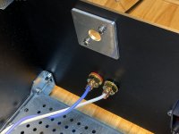
Hi wg45,
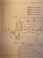
Connection goes directly to transformer input. That’s jumper JP101 pin marked with X and ground, as on this picture:

Connection goes directly to transformer input. That’s jumper JP101 pin marked with X and ground, as on this picture:
If i may offer an input as humble a novice- ive read tgat its a good practice to strip the ground plane under and around tge opamp because of parasitic capacitance from my experience it does make audible difference
Thanks, Tombo! It really couldn't be easier to make the connection. Input signal goes to the X connection of JP101 and the ground to ground.Hi wg45,
Connection goes directly to transformer input. That’s jumper JP101 pin marked with X and ground, as on this picture:
View attachment 1027738
Just to make sure I understand, we are bypassing the LuDef input buffer. All the components "in front" of JP101 can be left open. So, no need to install-
R101-106
J101-106
P101-102
Thanks again!
Sure. If your ears can pick up short wave radio frequencies, it will certainly sound better.If i may offer an input as humble a novice- ive read tgat its a good practice to strip the ground plane under and around tge opamp because of parasitic capacitance from my experience it does make audible difference
I’m not that gifted.
Picofarad or two have absolutely no effect in audio band or even hundreds of kHz, as shown on 100 kHz square wave response.
Yes, but maybe you should assemble PCB as designed to have comparative choice. On the other hand, it will cut assembly time considerably. 🙂Just to make sure I understand, we are bypassing the LuDef input buffer. All the components "in front" of JP101 can be left open.
Everything inside red encircled zone on attached schematic doesn’t need to be installed if other input buffer will be used.
Attachments

A lot of the evaluation boards from major companies are done the same way. Maybe pico farads does absolutely make difference either directly or indirectly. Or maybe all these engineers are running an industry scale gag on us
Last edited by a moderator:
Donovas,All the evaluation boards from major companies are done the same way. Maybe pico farads does absolutely make difference either directly or indirectly. Or maybe all these engineers are running an industry scale gag on us
I advise you to open specific thread on this topic and enjoy ideas and experience exchange with interested participants. I’m not one of those.
I thought suggestions and feedbacks were always a welcoming prospect. I didnt realize you designed a perfect board my apologies.
- Home
- Amplifiers
- Pass Labs
- Input buffer for LuDEF, SissySIT and similar amplifiers