@tvicol I hope the below schematic per your layout guide PDF is the correct and we can follow the same as the PCB silk screen seems to have some issues in the boards that I have printed. Per the below schematic Q3/7/12 is 2SC2240 which equals KSC1845 and Q2/10 is 2SA970 which equals KSA992. I hope I got the replacements right and also per your BOM suggestions. The only confusion is if you look at the page #7 the "Bill of materials" section the numbering seems to be wrong as 1845 you mentioned as Q2/7/12 and Q10 as 992.

https://github.com/tvicol/Q17-a-QUAD405-audiophile-approach/blob/main/Project description.pdf
https://github.com/tvicol/Q17-a-QUAD405-audiophile-approach/blob/main/Project description.pdf
Last edited:
They are from a known source and I have tested these mosfets in most of my Salas BiB builds successfully. So i know that they are genuine and works fine.Your FQP3P20 looks strange. It looks like there should be notches in the substrate
R29\R30что приведенная ниже схема в соответствии с вашим руководством по компоновке в формате PDF верна,
I need to verify the Q2/3/7/10/12 transistors for KSC1845 and KSA992 as seems like I got confused and its very late here. Will take a look again fresh for these transistors and report back.
Thanks
Thanks
There's been 10 ohms and 100 ohms.Я использовал резистор на 10к.
Very reminiscent of the 1973 Wireless World amplifier by JR Stuart. ( https://keith-snook.info/wireless-w...973/An approach to audio amplifier design.pdf )
Hello Tibi,
I have learned from the last experiments. What I find remarkable is that at relatively low volume I managed to burn out the end transistors. Nothing else happened, as my 500VA transformer is fused at 3.15A on the mains side (so at about 700W, the fuse shut down the amplifier).
From the remains of the last 3 or 4 Q17s I disassembled, I built a new one today, which is playing superbly again. I further expanded my concept in the process. This time I increased C1 from 470pF by 150pF and added an inductor of 3.3 uH in series with R6, but left my snubber of 15nF and 499Ohm in parallel.
Regarding the starting problems of the experiments here, I had them several times, for me it works well when R29 is slightly smaller than R30. R29 + R30 in 330 ohms destroyed the Z-diodes D5 and D6 for me.
I reduced C13 and C14 to 150uF, R29 = 8,2k and R30=10k.
For testing I use a transformer with 60VA and 2x24V AC, which is then 2x35V DC. One module from the current setup consumed 7W at idle. One has 36mV offset, the other 39mV offset.
I still haven't bought OPA1641, my Q17 always have to play with the OPA1611, this increases the oscillation potential!
The current one plays very very well, a bit more neutral than my previous models.
Less analytical like one and less tube sound like the other, something in between.
Regards Tim
@tvicol I hope the below schematic per your layout guide PDF is the correct and we can follow the same as the PCB silk screen seems to have some issues in the boards that I have printed. Per the below schematic Q3/7/12 is 2SC2240 which equals KSC1845 and Q2/10 is 2SA970 which equals KSA992. I hope I got the replacements right and also per your BOM suggestions. The only confusion is if you look at the page #7 the "Bill of materials" section the numbering seems to be wrong as 1845 you mentioned as Q2/7/12 and Q10 as 992.
Look at this uptodate diagram.
It must match your PCB (except Q12/R42/R43) with the same numbering but with references of available component.
https://github.com/stefaweb/Q17-a-QUAD405-audiophile-approach/blob/main/Q17-Mini-schematic.pdf
Regards,
Stef.
I went with the Github schematic pdf file of Tibi and its mentioned as 10k. I need to change this to 100R and retest the amp with bulb tester. Thanks for pointing this out maybe I read this change somewhere in this long thread but completely forgot about this while soldering 🙂Yes, R29\R30 @ 100 Ohms works fine !
Thanks
Also on the input signal pins, I see an arrow and I presume thats the RCA signal input and the other pin is the signal ground. Please confirm anyone who is using the original Tibi boards.
Thanks
Thanks
From the pics , it seems the input jack pin closer to the 1uf capacitor is the
signal - you will see a track on the PCB connecting it to R16.
The other pin (towards the edge of the PCB) is ground.
signal - you will see a track on the PCB connecting it to R16.
The other pin (towards the edge of the PCB) is ground.
Yes got it the pad goes to the R16 (22k) which I will take as signal input and the other pad as signal ground. But not sure why does the ground signal pad has that arrow 🙂From the pics , it seems the input jack pin closer to the 1uf capacitor is the
signal - you will see a track on the PCB connecting it to R16.
The other pin (towards the edge of the PCB) is ground.
Thanks
One quick update, removed the 10k resistors and replaced with 100R on R29/30. Now with the bulb tester across the 0.1R in series with the positive rail I get only 0.1mV but the bulb is still glowing. Offset is around 0.1mV and the FQA36P15 power mosfet is getting warm but the opp mosfet is not getting warm during this test after 10-15mins. Voltages across the 47/1w resistor is around 2.32v. Rechecked all the transistors and they all seem to be fine and no shorting anywhere. Any other pointers in terms of why the bulb tester is not switching off or should ideally glow less brighter with now less than 0.1mV flowing right now.
Thanks
Thanks
Hello Tibi,
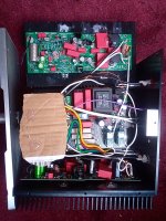
a picture of the current setup.
Looks bad, I took an existing board and the small lump of hot glue is L2 (I had to wind something with 33 turns myself). The red blocks on the board in the output are Wima MKP10-630 680nF, only with them the tweeter is super clean. Before that I had only installed Wima FKS3 with 220nF, which was not ultra good.
Test song is e.g. Annett Louisan - Wir sind verwandt 13s to 19s.
This is the second part of the intro in which knives are sharpened in the background.
Regards Tim
Attachments
That arrow is from footprint connector. I'll rotate this, so will not create further confusion.Yes got it the pad goes to the R16 (22k) which I will take as signal input and the other pad as signal ground. But not sure why does the ground signal pad has that arrow 🙂
Thanks
As it is now, will indicate ground input signal.
Regards,
Tibi
Last edited by a moderator:
- Home
- Amplifiers
- Solid State
- Q17 - an audiophile approach to perfect sound