I don't understand. How would another identical stage limit the other half ( I presume you mean the negative side) of the signal?That will take care of limiting the other half of the signal
If it`s an inverting stage (like I made) then the negative half coming from the first stage will be output as the positive half on the following stage. Why would we want to do that instead of limiting both halves with one stage? You can put a volume and/or tone circuit in between and this will change the characteristics of harmonic distortion developed. Not talking heaps of distortion with these types of circuits, it`s very subtle, low order harmonics.How would another identical stage limit the other half ( I presume you mean the negative side) of the signal?
But if you hit it with a bigger clean signal at the front end it will get more distorted at the output but should behave itself quite gracefully..it`s not a sudden onset of clipping. If you soft limit one half of the waveform on the FET stage, for a big signal input you will likely clip a little harder the other half at the extreme..but that happens with tubes as well. It won`t sound like a can of bees buzzing.
More nonsense and ZERO evidence to support your (wrong) claims!There's nothing extraordinary about springy materials tending to resonate at certain frequencies. Well, there kind of is, seeing as it's the basis for how tones are made, but nearly everyone here seems to be dismissing musicality and the evidence of their own ears as inferior to some pet theory of how they think physics works.
Brute force control of cone position with no regard or upper limit to the force required to achieve that side-goal leaves the system wide open to misbehave. The crux of the problem is what happens at resonance. Not the normal ~90dB efficiency at the 'tight' frequencies, but the ~100dB+ of the occasional long notes that seem to ring "because of the room". Higher efficiency goes together with the cone having more leverage over the air, basically 'throwing' it like moving your hand 5cm to 'throw' the other end of a slinky spring 20cm. (Basic horn theory. It's much, much more than just narrowing the dispersion angle.) When that happens, the residual SPL added when the MFB applies more force to counteract the 'errors' introduced by the nearfield SPL at resonance starts to add up.
Can you see how the polarity of the feedback is positive? The MFB speaker actively adds more SPL in response to fractional errors caused by already-high SPL.
If you can't provide evidence (measurements) about your extraordinary claims about MFB speakers, please stop embarrassing yourself with those laughable "explanations".
The speakers in question were auditioned - listened to. There was plenty of "evidence of their own ears"....everyone here seems to be dismissing musicality and the evidence of their own ears as inferior to some pet theory of how they think physics works.
Secondly, the beautiful thing about physics is that it doesn't matter how you think it works.What matters is that it does work, not what you, or I, or anyone else, thinks. The proof is in the actual measurements. Before Galileo, everyone believed a heavier rock fell faster than a lighter one, because Aristotle had said so, and he was the ultimate authority.
Well, Aristotle's thoughts were wrong. Everyone who believed him was wrong. Galileo did the actual experiment, and found out that all objects fall at the same rate in vacuum.
Think about this for a moment: you think the additional force from MFB on the speaker cone has a dramatic effect on the Q of acoustic wave modes in the room. Well, every square foot of wall in that room applies force to the air, and exactly the same type of force - an opposing force proportional to the incident force.
So why would you think the one square foot of speaker cone area would have more effect, than many hundreds of square feet of wall area?
This belief simply doesn't stand up to any scrutiny. It makes no sense. And, as anyone who's had any dealings with room acoustics knows, in fact, it is the walls that are crucial. Rooms with hard walls (tile, glass) have very strong acoustic resonances. Rooms with walls with softer finishes, covered in drapes or carpet, have more subdued resonances.
In a nutshell: room acoustics are controlled by the walls, floor, and ceiling. Not by the loudspeakers in the room.
-Gnobuddy
I agree, the key being to keep the audio signal quite small, so it traverses only a small part of the diode characteristics.Diodes don't necessarily hard clip or sound harsh, if you're careful.
Many years ago, I came across a circuit that used a single diode to "warm up" the sound of an audio signal, for those who like their music coloured and not Hi-Fi. The circuit split the incoming audio signal, fed a tiny bit into a diode, then mixed the resulting slightly distorted signal back in with the main signal.
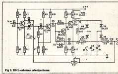
Even more dramatically, in the 1970s, before Dolby Noise Reduction, Philips designed, manufactured, and sold their Dynamic Noise Limiter (DNL) to reduce tape playback hiss. The clever circuit used several diodes as variable resistors, while creating negligible amounts of distortion from them. The goal was that you wouldn't hear any distortion at all, only hiss reduction.
I'll attach the Philips DNL schematic, for anyone curious. I built one a long time ago - it worked quite well, reducing the tape hiss from my DIY cassette deck quite noticeably. The clever part was that it responded to audio signal level and frequency content, basically turning down the treble only when there was no appreciable music content at those frequencies.
So yeah, if you keep the audio signal well controlled, you can stay away from harsh diode clipping. In fact you can keep distortion inaudibly low, or nearly so, with careful design. (Not the goal for guitar, but possible.)
This is not how diodes are used in most SS guitar circuits, though. The two configurations I've seen most often are either NFB around a high-gain amplifier stage via a parallel pair of back-to-back diodes (design roots go back to analogue logarithmic amplifiers from the era of analogue computers, an idea borrowed for the Big Muff), or a parallel pair of back-to-back diodes shunted across the signal, from signal to ground (like the Proco Rat and its endless clones).
To my ears, both the Big Muff and the Rat generate unpleasant harsh distortion on their own. David Gilmour seems to have been the first to discover that if you follow a Muff with a delay, you can "smooth out" the harshness and generate the beginnings of a beautiful, violin-like tone.
-Gnobuddy
Attachments
Have you seen the schematic of the Wampler Plexi Drive? (There's one a few posts from the start of this thread: https://www.diystompboxes.com/smfforum/index.php?topic=115814.0 ).So what can be done following the ''squishy'' JFET stage? Add another one of course! 🙂
There's a nicely played demo on You Tube:
You can hear dynamic timbre changes and duty cycle modulation in the output of the Plexi Drive, so that it sounds much better than the buzzy, unvarying drone of a Tube Screamer or Rat type diode clipper (those produce perfectly symmetrical clipped waveforms with no duty cycle modulation).
The schematic in that thread may or may not be correct, as it was traced by someone who owned one of those pedals. Most attempts at copying that circuit did not turn out well, but I think this was simply because of wide JFET parameter tolerances.
I think Brian Wampler was chuckling to himself, watching amateur attempts to copy his pedal fail, as not many people who attempted to duplicate his circuit seemed to understand how to select and/or bias JFETs properly so they would work properly in his circuit.
If you replaced the fixed 1k source resistors with, say, 5k trimpots, the Plexi Drive might provide a nice starting point for your experiments.
-Gnobuddy
As you mentioned, most SS guitar amps resort to diodes in NFB directly across a high gain stage or shunting to ground, for the 'distortion circuit', and have a clean setting that's completely void of any distortion. There is little or no graceful progression of overtones (low order harmonics) with varying level of guitar signals.. Our ears can pick up 10% distortion, but depending on what type and relative levels of harmonics are there, we can either find it harsh, fizzy, spattery, or warm, full, airy, detailed. Very subjective, but guitarists (at least the ones I appreciate) like to use the amp distortion as part of the voice of the instrument, literally riding the volume knob on the guitar to get a bit more edge and bite on certain passages. They can make notes sing..and much easier to do with something that can gradually increase distortion (with low order harmonics) than the clipping of waveforms.So yeah, if you keep the audio signal well controlled, you can stay away from harsh diode clipping. In fact you can keep distortion inaudibly low, or nearly so, with careful design. (Not the goal for guitar, but possible.
I am familiar with that type of preamp, there are a few similar tubes-to-fets iterations of it.Have you seen the schematic of the Wampler Plexi Drive?
Yes, putting in trimpots on the source resistance give a lot better control over the FET biasing. It sometimes messes with the corner frequency of the low frequency cutoff, but you can change the bypass capacitor and get it back in the ballpark.I think Brian Wampler was chuckling to himself, watching amateur attempts to copy his pedal fail, as not many people who attempted to duplicate his circuit seemed to understand how to select and/or bias JFETs properly so they would work properly in his circuit.
If you replaced the fixed 1k source resistors with, say, 5k trimpots, the Plexi Drive might provide a nice starting point for your experiments.
I'll say that amongst many of the more known pedal builders, Brian is pretty cool about helping explain this type of circuitry to people who are interested. We have had differing approaches, and opinions on some things..but he's always been respectful and polite when I have discussed things with him online (other forum), and with others as well.
I don't really like the sound of this thing. And I think I know why, here is a simulated waveform of an overdriven J201 stage as in the schematic:You can hear dynamic timbre changes and duty cycle modulation in the output of the Plexi Drive, so that it sounds much better than the buzzy, unvarying drone of a Tube Screamer or Rat type diode clipper
It sounds just as it looks. The problem with particularly the J201 is that it has a very low pinch off voltage, wich makes it clip quite early on the negative side unless you make special bias arrangements
Guitar sounds are always subjective. Some people loved this pedal, others didn't. We don't all like the same foods, either. 🙂I don't really like the sound of this thing.
Personally, I don't think the sounds from that pedal are beautiful, but I do think they are "less bad" than a lot of other solid-state distortion pedals and amplifiers. Especially when notes further up the neck are played, and the sound is less "buzzy" than the lower notes.
That particular Wampler Plexi demo, actually reminds me of the guitar sounds Eric Clapton and Duane Eddie created on "Layla and other Assorted Love Songs". To me, that album is not a benchmark of great guitar tone either, and the guitars sound fizzy and "spiky". But still not as harsh and fizzy as many SS guitar amps and pedals.
As you can guess from the term "Plexi" in the name, this particular Wampler pedal was intended to emulate a Marshall guitar amp from a certain era ( https://www.guitarworld.com/features/marshall-plexi-guitar-amps-everything-you-need-to-know ).
To me the Wampler Plexi doesn't sound anywhere near as good as, say, this Marshall 2204 clone, built with actual valves:
The 2204 itself made sounds that were very harsh for its time, which is why it became one of the definitive amplifiers for rock music, not jazz or country or other less-distorted genres.
Turn down the amplitude of your simulated drive signal a lot. What does the output waveform look like now?And I think I know why, here is a simulated waveform of an overdriven J201 stage as in the schematic:
In the video clip I attached to my previous post, you can hear the guitarist start out playing gently (maybe also with the guitar volume pot turned down). What we're hearing at that point definitely is not a rail-to-rail squarewave.
Driven gently, JFETs produce nice smooth low-order distortion. But, in my experience, they don't have the huge headroom and very gradual overload of a real vacuum tube. Overdrive the JFET, and the smooth distortion quickly turns fizzy - but, IMO, still not as nasty as clipping diodes.
I think a big part of this lack of headroom comes down to the relatively low voltages these FETs can handle. Often JFET-based guitar pedals are run on only 9 volts DC. This is terribly inadequate.
I've obtained better results running JFETs on two 9V batteries in series, for 18 Vdc. But 18V is still tiny compared to the 250-350 volts found in a tube preamp.
Earlier in this thread, I mentioned the Russian engineer (KMG) who came closer than anyone else to making FETs sound like actual vacuum triodes. One of the things he did was to use high-voltage MOSFETs, and run them at the same 300 - 350 volts DC as the tube preamps he was trying to emulate.
That Wampler Plexi pedal has multiple FET stages in cascade, and the later stages are going to get driven pretty hard even with gentle guitar playing. But you can hear the distortion change and "breathe" as preceding stages start to overdrive or clip, so there is quite a lot of dynamic variation of timbre with playing intensity.
IMO, the Wampler Plexi sounds much better than the ever-popular Tube Screamer and clones.
I think the J201 was popular with guitar pedal designers, exactly because of its low Vp. When you're working with only a 9-volt power rail, you can't really afford to have 3 volts eaten up just to bias the source. Also, lower Vp usually translates to higher transconductance, and more voltage gain per stage when you only have 9V to power the thing with.The problem with particularly the J201 is that it has a very low pinch off voltage, wich makes it clip quite early on the negative side unless you make special bias arrangements
One interesting thing to keep in mind: in most of Leo Fender's classic tube guitar amps, the vacuum triodes in the preamp are only biased to about 1.5 volts (Vgk = -1.5 volts).
JFET manufacturers seem to have focused on switching applications, not audio amplification, so every newer FET design has even more abrupt turn on / cut off characteristics. Exactly the opposite of what we would like for guitar audio.
-Gnobuddy
The attached waveform is from a J112 (JFET), in common-source mode, powered from two 9V batteries wired in series (18V total).
This is an actual waveform captured with a USB scope. It is not a simulation.
Input signal amplitude was turned up until the output was just shy of clipping. As you can see, there is no harsh/abrupt clipping in the output waveform at all.
There is also quite a lot of distortion in the screenshot, so you can turn down the input level and still get some "warmth" added to the guitar clean tones.
It's been a couple of years since I made these measurements, and I may have forgotten some details. I'm pretty sure I was using 10:1 'scope probes, so the output waveform was about 12 volts peak-to-peak.
I didn't record the input signal amplitude, but I do remember that the J112 FET produced far more voltage gain than older JFET types in the same circuit. The J112 produced about 30 dB of voltage gain, compared to something like 10 dB - 12 dB from, say, a 2N3819 in the same circuit.
-Gnobuddy
Attachments

Yes, and it sounds good, most people would agree. But why design an overdrive pedal using parts that do not sound nice when overdriven?Driven gently, JFETs produce nice smooth low-order distortion.
One interesting thing to keep in mind: in most of Leo Fender's classic tube guitar amps, the vacuum triodes in the preamp are only biased to about 1.5 volts (Vgk = -1.5 volts).
Triodes have grid current clipping, Jfets do not. The artificial grid current in the designs of KMG and others make sure soft clipping on the negative side happens before Vp becomes a problem. But in almost all pedals using jfets this problem is not addressed.
I really wonder that you were so amazed by the philips DNL. I built it at that time and fitted it into my Revox A77. Yes, it reduced the residual noise. But after a few days I removed it as it made the sound dull to me.I agree, the key being to keep the audio signal quite small, so it traverses only a small part of the diode characteristics.
Many years ago, I came across a circuit that used a single diode to "warm up" the sound of an audio signal, for those who like their music coloured and not Hi-Fi. The circuit split the incoming audio signal, fed a tiny bit into a diode, then mixed the resulting slightly distorted signal back in with the main signal.
Even more dramatically, in the 1970s, before Dolby Noise Reduction, Philips designed, manufactured, and sold their Dynamic Noise Limiter (DNL) to reduce tape playback hiss. The clever circuit used several diodes as variable resistors, while creating negligible amounts of distortion from them. The goal was that you wouldn't hear any distortion at all, only hiss reduction.
I'll attach the Philips DNL schematic, for anyone curious. I built one a long time ago - it worked quite well, reducing the tape hiss from my DIY cassette deck quite noticeably. The clever part was that it responded to audio signal level and frequency content, basically turning down the treble only when there was no appreciable music content at those frequencies.
So yeah, if you keep the audio signal well controlled, you can stay away from harsh diode clipping. In fact you can keep distortion inaudibly low, or nearly so, with careful design. (Not the goal for guitar, but possible.)
This is not how diodes are used in most SS guitar circuits, though. The two configurations I've seen most often are either NFB around a high-gain amplifier stage via a parallel pair of back-to-back diodes (design roots go back to analogue logarithmic amplifiers from the era of analogue computers, an idea borrowed for the Big Muff), or a parallel pair of back-to-back diodes shunted across the signal, from signal to ground (like the Proco Rat and its endless clones).
To my ears, both the Big Muff and the Rat generate unpleasant harsh distortion on their own. David Gilmour seems to have been the first to discover that if you follow a Muff with a delay, you can "smooth out" the harshness and generate the beginnings of a beautiful, violin-like tone.
-Gnobuddy
I agree with you, and particularly if the goal is to build a solid state guitar amp, then the JFET preamp section run at 18 to 24 VDC would make sense.I've obtained better results running JFETs on two 9V batteries in series, for 18 Vdc.
Would not it depend on the signal level whether it was soft clipping?Yes, and it sounds good, most people would agree. But why design an overdrive pedal using parts that do not sound nice when overdriven?
Triodes have grid current clipping, Jfets do not. The artificial grid current in the designs of KMG and others make sure soft clipping on the negative side happens before Vp becomes a problem. But in almost all pedals using jfets this problem is not addressed.
But are there any solid-state parts that do sound nice when overdriven hard?...why design an overdrive pedal using parts that do not sound nice when overdriven?
I don't think there are. Compared to triode (vacuum tubes), all solid-state amplifying devices clip hard.
And if you drive vacuum triodes or pentodes too hard, they will clip pretty hard too, especially pentodes.
For analogue solid-state "subtle distortion", I think using JFETs is "making the best of a bad job", as old English books put it. They are the "least-bad" semiconductor device when it comes to hard, harsh, clipping.
To take advantage of the "least bad" characteristic, I think the only way to get relatively gentle clipping from solid-state devices is to limit maximum input signal amplitude in some way.
With multi-stage circuits (like the Wampler Plexi), the easiest way is to use two resistors to make a voltage attenuator in between the output of every stage, and the input of the next one. Choose the attenuation ratio so that when the preceding stage is driven to full output, the next stage is overdriven, but not so much that it sounds harsh.
But Brian Wampler knows his market. Probably he knows that there are lots of teenage boys and young men who grew up with various flavours of metal music, and they will buy harsh-sounding distortion pedals, while only a few old codgers will buy a pedal that produces subtle, singing distortion.
JFETs do indeed have gate current clipping. The gate-channel interface is an ordinary semiconductor PN junction, a diode, and it will conduct if biased the right way. (Or wrong way, depending on what you want it to do!)Triodes have grid current clipping, Jfets do not.
For instance, an N-channel JFET will start to flow gate current if you allow the gate to become about 0.6 V more positive than the source. The current then rises exponentially with rising input voltage, just like any other semiconductor diode.
This is what allows the JFET source follower to accept a bigger-than-rail-to-rail input without harshly clipping the output,
KMG's artificial grid current will also squash positive-going peaks from the preceding stage, because it has a high output impedance. The typical Fender (tube) preamp stage has an output impedance of roughly 40 kilo ohms, while KMG's artificial triode has an even higher output impedance, two to two-and-a-half times as high.The artificial grid current in the designs of KMG and others make sure soft clipping on the negative side happens before Vp becomes a problem.
I wonder what happens if you run a JFET on very low DC supply voltage. I suspect progressive (FET) channel saturation will cause relatively soft clipping on negative half-cycles of the output, at least for older JFET designs (MPF 102, etc).
Newer JFETS are increasingly more and more like on-off switches, without much linear range in between.
-Gnobuddy
No. So when you want to use them anyway, you heve to think of ways to make them sound nice.But are there any solid-state parts that do sound nice when overdriven hard?
But a jfet stage will clip (not very soft) on the negative output long before this, simply because the output voltage cannot go lower than Vpinchoff + 0.6 volts. So you have to do something to make it clip more gracefully before that happens.JFETs do indeed have gate current clipping.
Can you design something that works better, with so few components, and only those components readily available in 1970? And using only inexpensive components from that era, at that?I really wonder that you were so amazed by the Philips DNL.
I still think the Phillips DNL was a very clever circuit for its time. For one, generating a level and frequency sensitive DC control signal in response to the very complicated signal that is music, without audible artifacts, is a difficult challenge.
AFAIK, only Ray Dolby had done that job well before, and he was using more expensive and more exotic components (a JFET as VVR), along with a lot more components and complexity. His original noise reduction system was so complex it was extremely expensive, and only used in recording studios.
For another, using ordinary semiconductor diodes as variable resistors in the DNL was quite a clever trick, keeping costs and complexity down, while providing acceptable performance for the era.
Oh, how frustrating the always-dull sound of tape was!...after a few days I removed it as it made the sound dull to me.
This was a permanent problem with all consumer reel-to-reel and cassette players right up till the last dying years of the technology. It was one of those frustrating technological limitations that never really went away, until video tape recorders began to include ways of recording truly Hi-Fi audio, using rotating tape heads, and a frequency-modulating the audio onto an RF carrier signal that was recorded to tape.
VHS, Beta, and 8mm video recorders all came up with systems like this. For some years, the only way to get a truly Hi-Fi home audio recording, was to use a video recorder!
Before the Hi-Fi Audio video recorders arrived, to get adequate treble response from linear tape (i.e. not a VCR), you needed high tape speed, a magnetic playback head with an incredibly tiny and precise magnetic "gap", a perfectly clean playback head, perfect alignment between record and playback head gaps, and a "just right" recording level. Only rarely did all the planets align.
Yes, the DNL did make dull-sounding tapes sound even more dull. At one point I took the clever ideas Philips engineers put into the DNL, and made the opposite circuit: a dynamic treble booster for my DIY cassette deck. Instead of cutting treble during quiet passages, my variant boosted treble on loud passages, when hiss was less likely to be audible.
This did make the music sound brighter, but it also introduced audible artifacts - from time to time, you could hear the treble "breathe" as it faded back down after a loud passage. I didn't do as good a job with my level-and-frequency-sensitive detector circuit as Ray Dolby or the nameless Philips engineer beh
Some years after I built my copy of the Philips DNL, Dolby B noise reduction began to appear, but only on expensive equipment. Eventually, after a lot of hunting, I found a Dolby B NR schematic using discrete transistors in a library book.
(There were already Dolby B NR integrated circuits, but only available to corporations with Dolby licences - not to penniless kids obsessed with audio electronics.)
Building my own Dolby B NR from scratch was a bigger challenge than building the earlier DNL. Not only was the circuit much more complex, it required an audio signal generator and a multi-meter to adjust properly: I had neither! Also, the specified JFET wasn't available in any of the three local electronics shops in my town. In fact they only carried one single JFET type, so that was the one I had to use. I no longer remember the part number, but most likely, it was the good old MPF102
But in the end I made my own PCB (stereo, so twice as many parts and twice as many holes to drill by hand), built the circuit, and adjusted the trimpots as best I could by ear, using pre-recorded audio cassette tapes that already had Dolby B encoding on them. Ray Dolby would not have been happy with the way I built or adjusted my copy of his famous circuit, but it was much better than no noise-reduction at all!
It boggles my mind that people still complain about digital audio (first the CD player, then WAV and FLAC files). Have these people forgotten how very bad tape and vinyl audio equipment was?
-Gnobuddy
+1000 😀😀😀It boggles my mind that people still complain about digital audio (first the CD player, then WAV and FLAC files). Have these people forgotten how very bad tape and vinyl audio equipment was?

- Home
- Live Sound
- Instruments and Amps
- Building a SS guitar amp