Yeah wavelength of ~1khz is about ~12". First mode/standing wave between two walls is 1/2 wavelength, which would be ~1kHz for ~6".
Making box a transmission line is possibility. Internal walls make longer paths inside the box making even lower modes and harder to tame with damping material so it feels counterproductive though. I'm not into transmission lines so never thought if there was opportunities to reduce problems with modes. Perhaps, if the woofer position on baffle can be other than middle while location of the internal wall adjusts where the middle point is to kill the lowest mode. Otherwise its not gonna help, only make one more even worse problem. Perhaps position of the woofer in relation to mode pressure / velocity node has meaning in which case with transmission line one could position the driver on a position where a standing wave doesn't affect the performance.
Thinking it through: Problem is, the wavelength of first standing wave is bigger than box so there is no obstruction you can fit inside the box that would have much effect on the first mode. Even though there was internal panel(s) dividing the box the box dimension modes probably still exists but in addition there is now this longer path around the obstacle with even longer mode. Remember, the damping material is usually effective and if there is problem it is the lowest mode.
Anyway, I'm not too familiar with transmission lines so perhaps reasoning fails here. Transmission lines are usually open at one end to lower the resonance from 1/2wl to 1/4wl? And even longer to get the lowest mode augment drivers low end response. But with small boxes, where the modes are few hundred hertz range, mid frequencies of 2-way box, this is not helpful. Perhaps if the box was designed as TL from get go it would work out fine as you suggest, the lowest mode(s) would boost the bass while there would be enough room to damp the higher modes with damping material.
Last edited:
Hornresp shows that woofer (or acoustic center of woofers) mid way a dimension prevents the mode happening so if woofer is center of baffle only the front / back first mode happens.
yes, exactly, even kef is doing this in their ls50s
i think cubes are fine, i can not think of any shape that is more volume efficient, biggest volume inside while with the smallest exterior, a sphere might be even more efficient but very tricky to build
Cones used to be lighter, and with higher Q, so were probably less effective at stopping the backwave from escaping through the obvious soft spot. However, there's no free lunch as they say.Never found it made a difference in practice, especially with sufficient bracing and enough and well placed stuffing. I think, based on experience, that GR is mainly mythology.
Years ago, I built Accuton bookshelves, naively hoping to really lock that backwave down with rigid cones made of advanced materials. The result was a backwave which -- although faint in amplitude -- really screamed in longevity. It was only years later that I really thought to consider playing around with damping factors to absorb that sort of thing electrically.
Block more -> reduce gain but increase q
Block less -> more comb filtering but lower q
My most recent creation uses Mark Audio CHN-50's in a pair of cubes with equilateral triangles cut from each corner (cuboctahedron), about 4L, braced, and made with 6mm ply! Although the boxes seem to rattle like crazy, they don't seem to add any 'colour' or sound of their own. The low cost cotton wool damping is also incredibly neutral.
Last edited:
I'm aware, I didn't start doing this yesterday.Cones used to be lighter, and with higher Q, so were probably less effective at stopping the backwave from escaping through the obvious soft spot.
I'm still holding my opinion on that stuff as it's hard to get here affordably.The low cost cotton wool damping is also incredibly neutral.
Maybe it's a matter of sourcing? I used most of 2x 100g packs @ about 4zł ($1) a pop from a medical / cosmetics corner shop next to the makeup section. But even that cost twice as much as the viscose variety which is less absorbant.I'm still holding my opinion on that stuff as it's hard to get here affordably.
Oh, do you mean like cotton wool?Maybe it's a matter of sourcing? I used most of 2x 100g packs @ about 4zł ($1) a pop from a medical / cosmetics corner shop next to the makeup section.
I thought you meant the shredded denim based stuff that seemed to be the rage a while back.
Attachments
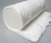
Yeah cotton wool! Sometimes simple is best.Oh, do you mean like cotton wool?
I thought you meant the shredded denim based stuff that seemed to be the rage a while back.
Thank you, that makes sense.Yeah cotton wool! Sometimes simple is best.
Just wondering what performance advantage it offers over good old fibreglass for sealed enclosures.
So, I think I have reached a compromise I won't flog myself over.
Firstly I removed all damping and dividers and measured. Then I moved the internal divider from infront of vent to behind the driver with some rockwool to damp reflections. It has given a much better alignment response. It matches my original sim which may be what made me throw my toys out the pram.
Green is undamped/undivided cab
Orange is divider behind driver with damping to top and bottom of cab and rear of driver

Undamped/undivided vs sim

Damped/divided vs sim
Still a bit troublesome around 300hz but the datasheet FR does not match mine and I can't find another near field measurement to compare to

Green is undamped/undivided cab
Orange is divider behind driver with damping to top and bottom of cab and rear of driver
Vent measurements

Undamped/undivided spectogram

Damped/divided spectogram

Far field measurement at 90cm/4.3ms gated merged with near field (NF has had baffle step curve applied in Vituix)

Datasheet FR

What are your thoughts? Could you live with this?
Firstly I removed all damping and dividers and measured. Then I moved the internal divider from infront of vent to behind the driver with some rockwool to damp reflections. It has given a much better alignment response. It matches my original sim which may be what made me throw my toys out the pram.
Green is undamped/undivided cab
Orange is divider behind driver with damping to top and bottom of cab and rear of driver
Undamped/undivided vs sim
Damped/divided vs sim
Still a bit troublesome around 300hz but the datasheet FR does not match mine and I can't find another near field measurement to compare to
Green is undamped/undivided cab
Orange is divider behind driver with damping to top and bottom of cab and rear of driver
Vent measurements
Undamped/undivided spectogram
Damped/divided spectogram
Far field measurement at 90cm/4.3ms gated merged with near field (NF has had baffle step curve applied in Vituix)
Datasheet FR
What are your thoughts? Could you live with this?
Probably just the handling, and no concerns about it getting airborne for ported boxes.Thank you, that makes sense.
Just wondering what performance advantage it offers over good old fibreglass for sealed enclosures.
grahamgraham, good results for sure! The problem seems to be gone without much penalty on the low bass, looks like less than the previous setup on post #184. Damping / divider arrangement here seems very effective.
Could you possibly post illustration / photo on the current setup, the divider and damping? I kind of said in my previous post dividers don't work so, would be valuable info perhaps !😀
I suspect this is very common issue with ported two way speakers and think most just don't mind about it, don't measure the finished speaker or don't see it in the measurements, or just don't find it valuable info worthy to publicly post about it.
Did you compare the sound? Was this dramatic improvement or not too much of a difference? I mean the port mid leakage is roughly -10db down in the worst case scenario, without damping. I've observed the leakage can be almost as loud as the Helmholtz resonance itself. edit. here is one, with divider panel and huge mid peak https://www.diyaudio.com/community/...ernal-standing-waves-and-port-leakage.362003/
Last edited:
Here you go, its just under half of the internal height with a gap at the top as to not create a TL path. It is located on the second brace about two thirds in to the cabinet. This is without damping behind the driver, the stapled on bit of earthwool was a failed experiment - it needed more.


None of it would have been retrofit possible without this darling little beauty:

The diagonal divider makes sense in the mind but from what I have tried and tested you don't need to be as fancy as cattering the waves, just block one whole chunk so there isn't a critical mass gatrhering/
None of it would have been retrofit possible without this darling little beauty:
The diagonal divider makes sense in the mind but from what I have tried and tested you don't need to be as fancy as cattering the waves, just block one whole chunk so there isn't a critical mass gatrhering/

I found some Faital Pro HF10AK drivers at a good price so got some measurements of both drivers today:


It was a bit of a comedy show today. I got all set up and started measuring then the water company started drilling up the pavement 3 meters in front of my house! Inbetween the racket I managed to put this crossover together:


A bit of ringing in thr 400hz region where I had the standing wave.

Distortion was just about 90db. The peak at around 1800hz seems to be common on all HF10AK measurements. Not a bad result but due to the noise today I am sceptical of anything under 400hz tbh.


A bit of ringing in thr 400hz region where I had the standing wave.
Distortion was just about 90db. The peak at around 1800hz seems to be common on all HF10AK measurements. Not a bad result but due to the noise today I am sceptical of anything under 400hz tbh.
I have redesigned the crossover for 1khz as woofer is becoming to directional at 2khz and causing an off axis dip. Hopefully this should limbo under that issue. I won't have the front room to myself for at least a week so I have verified the 1khz crossover with a highly gated measurement and it matches sims. It sounds very very good.
In the meantime the sun briefly came out today and I was able to get some pictures for posterity:


I knocked some stands up earlier this week out of 18mm MRMDF. Not as sturdy as I was expecting but they will do for now and keep me in my wifes good books. I used some tilting adjustable M6 feet and threaded inserts. I still need to make the horn supports.
In the meantime the sun briefly came out today and I was able to get some pictures for posterity:
I knocked some stands up earlier this week out of 18mm MRMDF. Not as sturdy as I was expecting but they will do for now and keep me in my wifes good books. I used some tilting adjustable M6 feet and threaded inserts. I still need to make the horn supports.
- Home
- Loudspeakers
- Multi-Way
- 10" + CD/Horn 2-Way