Hi Kevin,We’ll do it! My family is in for helping. Being our first group buy, we would like to do a limited number and ship to only CONUS addresses. If it’s a success we could do another and possibly broaden the parameters.
I might want to put myself for two boards instead of one if that's allowed.
Thanks
Continental USA does not include Hawaii & AlaskaHi all,
forgive my ignorance, whats CONUS addresses??
Very nice the idea of standard 5X7" frame, Mark 🙂 I'm thinking to put the H2 on a similar base and make a desktop system for my laptop with FE127E...
Member Variac appears to be the most vocal advocate for certain sizes of PCB (post #455)
FYI the fab named JLCPCB only offers the double thick (2 ounce) copper option, for green boards. Black and other colors are only available with single thickness (1 ounce) copper. Different fabs may have different rules, of course.
FYI the fab named JLCPCB only offers the double thick (2 ounce) copper option, for green boards. Black and other colors are only available with single thickness (1 ounce) copper. Different fabs may have different rules, of course.
This for creating a mount in a standard picture frame. Easy enough for me to adjust the board size if that is desired.
For a 5x7 frame the board size would be 5x7 but no components could extend to within 1/4" (really better 3/8") of the edge. I don't know how Variac intends to get the rest of the way. The picture frame needs at least 1/2" of depth from inside front edge of frame to back edge to accommodate PCB plus exposed wire ends. Then you need a base to attach the PCB to and then attach it to the frame.
It doesn't seem to be plug and play to me, but maybe I am missing something.....
-Tom-
It doesn't seem to be plug and play to me, but maybe I am missing something.....
-Tom-
As long as we’re tossing tuppences about, mine would be in favor of a smaller board, in keeping with the original mini moniker. 
Hey Mark,
I missed seeing the dimensions on your "almost clone" boards. The reason I ask is that I have two aluminum boxes which would make a good base for a smaller board.
-Tom-
I missed seeing the dimensions on your "almost clone" boards. The reason I ask is that I have two aluminum boxes which would make a good base for a smaller board.
-Tom-
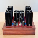
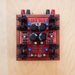
Another successful "Almost Clone" build - Thanks to Mark Johnson and Nelson Pass.
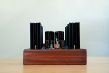
Completed the build last evening with IR MOSFETs. Sounds really nice. Here are some pictures of the build.
Wooden base was built by my son.
Completed the build last evening with IR MOSFETs. Sounds really nice. Here are some pictures of the build.
Wooden base was built by my son.
Attachments

What he said. Very nice work on both your parts!Beautiful build!
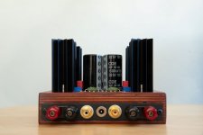
Very nice looking warm wood build and clean.
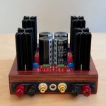
Quick question... what does the underside look like? Is it closed and boxed in with wires attached to the screwed in back plate or is it all open with the wires connected to the back plate that way?
Quick question... what does the underside look like? Is it closed and boxed in with wires attached to the screwed in back plate or is it all open with the wires connected to the back plate that way?
TomV, the boards for Group Buy #1 and Group Buy #2 , which are very ably organized and administered by @KevinHeem, are clones of Nelson's PCB, the one he gave away twenty copies of at Burning Amp 2021. Nelson showed its PCB layout in the .pdf attachments to post #1 of this thread. I cloned Nelson's board size and hole placement too; he provided a mechanical drawing in post #311 and 312 of this thread. Which I copied down to the nearest 0.25 mm.
Very nice looking warm wood build and clean.
Quick question... what does the underside look like? Is it closed and boxed in with wires attached to the screwed in back plate or is it all open with the wires connected to the back plate that way?
The underside is closed. The back side was routed using a trim router to a depth of 1" to screw in the back plate with connectors. The top was routed to 0.5" depth to mount the PCB.

- Home
- Amplifiers
- Pass Labs
- DIY ACA mini