And does it play music or sound like crap? When I biased with the wrong meter setting the heatsink was cold and the sound broke up.Are the heatsinks hot or cool to the touch? If hot you have more bias than you think. Also are you using the probes in both holes at VB?
Heatsinks are cold. Propes are in both holes.Are the heatsinks hot or cool to the touch? If hot you have more bias than you think. Also are you using the probes in both holes at VB?
Its worth noting I accidentally swapped the IRF9520 and IRF520 when I first built it, and powered it on like that, before realizing and swapping them back. Could that have broken the transitors?
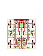
The IRF9520 and IRF520 installation can trick you if you are not paying attention. The pair face the same direction, but the direction is opposite on the other channel. Pay attention to the little bevels on the corners of what is printed on the board. That said both Mark and I fell into that hole and had to desolder and resolder a pair without ill effects.
Last edited by a moderator:
Yeah, as Tom said….. no fun desoldering them! Look closely at the board silkscreeen graphics to avoid doing this.
Then I had a bunch of problems biasing the left channel, and one output transistor was very hot!
Eventually turned the PCB over and discovered a monster solder bridge between two of the output transistor legs. I guess I fed a lot too much solder into the PCB holes for 2 of the legs! So glad it was something obvious! Seems to work fine now.
Mark
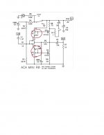
I have pairs at 8.5ma Jfet's I would like to use. I don't understand the concept of bridging the wiper and cw pins. In looking at the schematic it seems these pins are already connected in the circuit.They shipped with 6 ma idss. For less they might need a larger value on the pot.
If you use more than 7 ma I recommend bridging the wiper and cw pins on the pot to keep the Vds of the jfets at an adequate voltage. The idss limit on the jfets would be that of dissipation, but there is little advantage to the higher values
one way of looking at that:
A. put apart your thumb and middle finger and keep them that way; now move your first (pointing) finger between them
B. put apart your thumb and middle finger and keep them that way; connect your first (pointing) finger with thumb and keep it that way ; now move your middle finger all the way down and all the way up
in both cases thumb and middle finger are ends of trimpot, pointing finger is wiper
resistance is between thumb and middle finger, value of it according to distance between them
in case A - resistance is constant, you're varying position (thus voltage level, in most cases) of wiper
in case B, resistance is varying , as you're moving wiper (together with glued end) closer or further to solo end
put apart your thumb and middle finger and keep them that way; connect your first (pointing) finger with thumb and keep it that way ; now move your middle finger all the way down and all the way up
For greater effect, this should be done in traffic.
ACA mini calibration needs to be done slowly. In mine there exist only one setting that sets both the bias and center voltage where they should be. It's one of those situation where you need to make one worse with one pot to make it better with the other. 😒
I have pairs at 8.5ma Jfet's I would like to use. I don't understand the concept of bridging the wiper and cw pins. In looking at the schematic it seems these pins are already connected in the circuit.
I recall reading somewhere that the earlier art work was missing that connection.
Because the original artwork was missing that connection, I simply used jfets with less than 7 ma. With higher idss you might consider the bridge between wiper and cw pins. No big deal, future art will have it. By the time it reaches the store it will also fit a standard picture frame per Variac's request.
Great about it fitting a standard frame. Small frames can be had thick or thin and a multitude of finishes so something for everyone. The logical size is either 5”x5” or 5”x 7”. The existing board could almost be reduced to fit 5x5 but it’s already pretty tightly packed, and a minimum of 1/8” unpopulated is required around the perimeter as frames have a lip to retain the glass (or in this case the PCB). So 5x7 is looking to be right. That way Nelson can leave a minimum of 1/4” around the edges without any components or heatsinks so the board fits under the lip and doesn’t look cramped in the opening. Plus a bit more room to lay out parts to compensate for the unpopulated part. And maybe also some extra room on the front for text stating PASS ACAmini AMPLIFIER if he wishes.
A 5x7 board would also easily fit in (or mounted on) the same footprint sized HiFi2000 chassis as the ACP+ for those who like chassis’ and uniformity, and are willing to spend a bit more.
5x7 is probably the most popular frame size made also. Although no big deal I still vote for a board with black solder mask. (And one person agreed!) It shouldn’t cost more.
mark
Last edited:
- Home
- Amplifiers
- Pass Labs
- DIY ACA mini


