Not so much to say. First connect to high-impedance point, next connect termination low-resistance point.Since no one objected to my proposed PC board change
Sectioned El type at 1.5-2x bias idle power for as low as possible interwinding capacitance. Yes, typically it will be wounded at a core saturation limit, but remember our input resistors, they not only allows you to create a very efficient filter, but also very effectively dropdown induction to a moderate level.I need to decide on power transformers.
Yeah, the proposed change has that backwards, which is why I hesitated. If this were a high-speed or micro-stripline circuit, I would worry about reflections and parasitic inductance and so on. Not that I have any experience with high frequency circuit boards. I am convinced that these effects don't matter below 10MHz, which is well above the internal bandwidth of this amplifier. The wavelength is around 1000 feet at this frequency. Reflections still happen, but the phase angle differences are so small as to be insignificant, at least in theory.
I think you can go overboard fussing over PCB symmetry. There are plenty of fine amplifiers that aren't even close to symmetrical. The word that comes to mind is "precious." It can seem too self-conscious. It's time to just order boards and stop trying to impress the magazine photo editors.
There are some small transformer winders that do designs optimized for low noise. These features aren't just snake oil, though you still need to be careful in the overall layout to make the most of them. Of course, you pay extra for that. I need to do some research. I've had mixed results with name-brand transformers.
I have one more of my dual-mono, integrated Super Regulator boards left and a pair of 18-0-18V Talema 25VA transformers that fit. The raw supply makes about +-25V under load and the regulator wants about 5V drop across it, so I could start out with a 20V supply if I'm so inclined. I need to avoid putting too many parts buys on the credit card each month, lest the auditors at the War Department should become alarmed.
I promise, Mark, to build up the official regulator eventually and to find a source of quality transformers.
Yes. And next think about bridged output for keeping ground undisturbed.It's time to just order boards and stop trying to impress the magazine photo editors.
😉
Approach named allows to forget about specially wounded trafos and use any accessible. El better, then R-core, then toroids the last.find a source of quality transformers.
BesPav brings up an interesting point about using a briged output and I ask the question is it really necessary in a headphone amplifier. There are pro and cons here and understanding that a headphone is inherently balanced device there might be more down side to using an bridged output. The market requires manufacturers make balanced amplifiers which raises the question how many people use the bridged output but in the real world what do you gain. Just something to ponder.
Yea.There are pro and cons here
But since you'll listen to headphones without usual crosstalk on the common groung wire you can't get back.
So if we really go to 4-wire connection there are no need to have a ground at all. And it's better to decouple output power stage and ground also. No dumping current, no ground loops, no tricky routing, paradise as it is.
I like the idea of keeping ground currents from flowing back into the amplifier, but I think you can largely deal with that if you lay out your internal grounds right in the first place. The crosstalk problem can be solved by using a four-wire cable with the negative leads joined at the connector. I agree with Jam that much of the balanced amp hype is driven by marketing, as well as the irrational demand for high power output specs from small boxes.
On the other hand, if you believe that "everything matters," then there really isn't much to do except try it for yourself and see what happens. I don't want to make myself any more neurotic than I already am, so I'm doing all this in small steps. It's a hobby for me, not a full-time profession. As NP says, "It's entertainment."
These are all good suggestions, but I don't feel pressure to try everything all at once. TBH, It's a small miracle how productive I've been this past year on the hobby front. The price has been paying less attention to other important things, like maybe my job and my family, so I have to pace myself. I literally quit playing classical piano a year ago because I was spending all my time on the DCG3 project. I feel bad about that, need to do something about it. Piano lessons over Skype suck, though, which was a factor in the decision.
Anyway, it's all good. Once I prove out my board, I'll publish the Gerbers and then maybe someone can build a bridged version and report on the results.
Approach named allows to forget about specially wounded trafos and use any accessible. El better, then R-core, then toroids the last.
I keep reading pro-and-con arguments about EI versus toroidal transformers. I guess it boils down to tradeoffs between inter-winding capacitance, balance, and stray fields. Given all the conflicting reports, I imagine it depends on the particulars of the implementation. The pi RC filter sounds appealing, but some people will absolutely insist that adding primary resistance will bugger the supply. I have no way to decide.
Hi BesPav and Henry,
Granted your point ground issues but lets look at the advantages of of bridged circuit
a) twice the slew rate - is it really necessary?
b) four times the power -providing the voltage rails stay the same and power can handle it-but is that voltage swing necessary?
c) the ground issue advantage, but good design can negate most of this.
Now lets look at the single ended approach
a) do not have potential problems with a bridgeing circuit (methods of obtaining an inverted signal)
b) less than half the circuitary - all things being equal - hence half the cost assuming no shortcuts were taken
c) bridge circuits look at half the impedance of the actual load, so you have to beef up the output stage
Balanced bridge power amplifier have their advantages (speakers) but most of these advantages are not there when driving headphones.
I discovered that producing a balanced HPA-1 would cost almost three times as much with little if any sonic gain and some downsides.
Jusy saying.
Not to say I will not produce a balanced haedphone amplifier at some point but this will be done for marketing reasons and the ability to use it as a balanced preamp.
Jam
PS. this is not to say you should not have a balanced input. 😉
Last edited:


Well, I just ordered my boards from JLCPCB. I found about a half dozen things to fix tonight, none of them fatal errors. I'm sick of reviewing, so hopefully it's all good. I should get the boards early in the week after next.

I've gotten good at waiting. There's plenty of work to do in the meantime. The hardest part for me is worrying about the bad errors I didn't catch. I've had to throw away more than one batch of boards in the past because I realized only after it was too late to cancel that I'd done something stupid -- typically, symbols upside-down on the schematic.
These are the regulators I plan to start with. Mark will be very uncomfortable, as the amplifier will break in with high-feedback power supply electrons.

Edit: I think, if I do another run of boards, that I'm going to add a Darth Vader drawing to the silkscreen, to credit your design.
These are the regulators I plan to start with. Mark will be very uncomfortable, as the amplifier will break in with high-feedback power supply electrons.
Edit: I think, if I do another run of boards, that I'm going to add a Darth Vader drawing to the silkscreen, to credit your design.
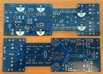
My own wait is over! This is a long and skinny layout of Henry’s A2 amp that is designed to be mounted to the walls of a 2U enclosure. I’ve also already found a problem that I didn’t spot before sending the gerbers off, but should be OK to work around it. I’m looking forward to finding some time this weekend to start the build..........the hard part is waiting.
Thanks Henry and others for a very enjoyable thread and to Henry for all of the comments and suggestions on the draft layout.
Looking forward to hearing about your progress on the A3! 🙂
Attachments
Aargh!.............I see integrated circuits's 🙄 🙂
I prefer to think of them as "Eight-Legged Helpers." 🙂
I've had good results in three different projects now with my version of the Jung/Didden Super Regulator. Assuming my layout is good, performance should be on par with the diyaudio store version, which in turn should outperform the HPA-1 Darlington follower on paper. Super Regulators are reputed to work well in subjective tests, but who knows what that means in this application?
My goal is to try different styles of circuits and see for myself if I notice a pattern in the sound signatures. As for becoming a world-class designer, hah, no way, man. The good news is, I've been able to listen to three DIY designs so far and will soon have a fourth to play with. It will be interesting to compare the two regulators.
My own wait is over! This is a long and skinny layout of Henry’s A2 amp that is designed to be mounted to the walls of a 2U enclosure. I’ve also already found a problem that I didn’t spot before sending the gerbers off, but should be OK to work around it. I’m looking forward to finding some time this weekend to start the build.
Awesome. I'm super keen to hear how this works out for you.
Captain B,
I hope you will send us pictures of your build......
What is an A2 amp...is there a link to the schematics, Henry?
I hope you will send us pictures of your build......
What is an A2 amp...is there a link to the schematics, Henry?
Hi, Jam. A2 is the new name for my HPA2/Cordell amplifier. It's the same as what I sent you privately a while ago. The schematic posted way back in this thread may be a little out of date, but for people who are interested, I can send a link to the latest Kicad files.


I don't remember if I mentioned this before, but there's a thread on the Solid State forum describing an ambitious power amp design based on the same Cordell schematic as my A2: https://www.diyaudio.com/community/threads/vfa-front-end-the-bunnyphant.369957/
The OP pulled out all the stops on this, including a diamond buffer output stage with four pairs of output transistors, multiple compensation networks, and every trick from Bob Cordell's book. Getting it stable has been a problem, but they've made progress.
I mention it because OP has been reading Kiwanuka's paper and the referenced "DCDS" circuit which has some similarities to Cordell's front end.

If you take a look at the compensation circuit in the lower center of the diagram, you see a single-ended TPC network, and then a 100pF capacitor labeled Cx. I've written here before about how my "flying" balanced compensation scheme in the A2 doesn't work as I thought it did because the mirror impedance on the left side is essentially an AC ground. With no voltage gain on this side, Miller compensation isn't happening. That's why Kiwanuka has Cx, and not a duplicate of C1/C2/R in his diagram, which I mistakenly tried to implement in my circuit.
As Kiwanuka points out, there are two signal paths through the front end, which are summed in the mirror, and if you only compensate one of them you end up with a non-minimum phase response and something less than the desired single-pole, -20 dB/decade response. So he puts in Cx and adjusts its value to get the optimum slope, combining the responses of both sides of the VAS.
I've been wondering why my compensation scheme works. It occurred to me just now that the left/lower leg of my A2 compensation network, being connected to a low-impedance node, is probably acting something like Kiwanuka's Cx. There's some real subtlety there because the compensation current goes into the mirror, not ground, and the resistor in the network is floating instead of connected to ground (or the rail).
In principle, you get much better PSRR keeping that resistor referenced to the supply rail instead of ground. That was my intent for the "flying" network to begin with. Somehow, this thing sorts itself out and ends up with the proper slope and phase shift, at least according to SPICE. You can see the simulated response is picture-perfect:

I'm nervous as always about releasing this design with a detail I don't understand and suspect is wrong, but I can't argue with success.
Another thing I learned recently is why my loop gain plots always show a rise above 10 MHz. I got some good information about this from another thread. I followed instructions on how to insert a voltage probe for loop-gain simulation from an LTspice video on YouTube. It turns out you really need a full Tian probe (it is left as an exercise for the reader...) if you want to get accurate results. Tthe partial probe I used doesn't account for current flowing in/out of the inverting input. The high-frequency rise is due to capacitive effects in the input pair which the Tian probe would account for. Fortunately, with JFET inputs, the input current is low enough not to seriously mess up the plot over most of the bandwidth of interest.
The Tian probe is much more work to set up in SPICE and I haven't gotten around to trying it yet. But I want to because I'd like to better understand the circuit behavior at the high end of the frequency spectrum.
I know this is a little esoteric, but I want to keep people up to date as I learn new things about this design.
The OP pulled out all the stops on this, including a diamond buffer output stage with four pairs of output transistors, multiple compensation networks, and every trick from Bob Cordell's book. Getting it stable has been a problem, but they've made progress.
I mention it because OP has been reading Kiwanuka's paper and the referenced "DCDS" circuit which has some similarities to Cordell's front end.
If you take a look at the compensation circuit in the lower center of the diagram, you see a single-ended TPC network, and then a 100pF capacitor labeled Cx. I've written here before about how my "flying" balanced compensation scheme in the A2 doesn't work as I thought it did because the mirror impedance on the left side is essentially an AC ground. With no voltage gain on this side, Miller compensation isn't happening. That's why Kiwanuka has Cx, and not a duplicate of C1/C2/R in his diagram, which I mistakenly tried to implement in my circuit.
As Kiwanuka points out, there are two signal paths through the front end, which are summed in the mirror, and if you only compensate one of them you end up with a non-minimum phase response and something less than the desired single-pole, -20 dB/decade response. So he puts in Cx and adjusts its value to get the optimum slope, combining the responses of both sides of the VAS.
I've been wondering why my compensation scheme works. It occurred to me just now that the left/lower leg of my A2 compensation network, being connected to a low-impedance node, is probably acting something like Kiwanuka's Cx. There's some real subtlety there because the compensation current goes into the mirror, not ground, and the resistor in the network is floating instead of connected to ground (or the rail).
In principle, you get much better PSRR keeping that resistor referenced to the supply rail instead of ground. That was my intent for the "flying" network to begin with. Somehow, this thing sorts itself out and ends up with the proper slope and phase shift, at least according to SPICE. You can see the simulated response is picture-perfect:
I'm nervous as always about releasing this design with a detail I don't understand and suspect is wrong, but I can't argue with success.
Another thing I learned recently is why my loop gain plots always show a rise above 10 MHz. I got some good information about this from another thread. I followed instructions on how to insert a voltage probe for loop-gain simulation from an LTspice video on YouTube. It turns out you really need a full Tian probe (it is left as an exercise for the reader...) if you want to get accurate results. Tthe partial probe I used doesn't account for current flowing in/out of the inverting input. The high-frequency rise is due to capacitive effects in the input pair which the Tian probe would account for. Fortunately, with JFET inputs, the input current is low enough not to seriously mess up the plot over most of the bandwidth of interest.
The Tian probe is much more work to set up in SPICE and I haven't gotten around to trying it yet. But I want to because I'd like to better understand the circuit behavior at the high end of the frequency spectrum.
I know this is a little esoteric, but I want to keep people up to date as I learn new things about this design.


- Home
- Amplifiers
- Headphone Systems
- New Headphone Amplifier Design