Here we go again; more Sony V-fet adventures
To save looking
Part 1 : https://www.diyaudio.com/community/threads/another-sony-ta-4650-v-fet-thread.376634/#post6775928
Part 2 : https://www.diyaudio.com/community/...aka-another-sony-ta-5650-v-fet-thread.379125/
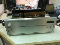
Hopefully, not being too clever for my own good I've plumped for a TAN-5550 Vfet power amp frpm Ebay Germany, so hopefully I understood the ad well enough, "Defekt" was pretty clear.
So no V-fets either and it's certainly been worked on at some point - no chimneys installed and some of the screws are missing. But the boards appear OK so it should be re-buildable.
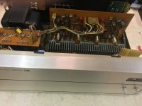
First impression is that Sony made NO attempt to use anything from the TA-5650, although the TAN-5550 could (should?) have been that, without all the extra stuff associated with a pre-section.... Anyway for 'reasons' there is a very different 'class A' board (including a couple of 2SK58 dual fets) and a completely different amp board. It's also entirely directly coupled throughout, which is nice.
As before, this thread is for my benefit in terms of documenting what I've done. Hopefully it's of use to anyone attempting the same thing. But this is how I did it (am doing it) 🙂
To save looking
Part 1 : https://www.diyaudio.com/community/threads/another-sony-ta-4650-v-fet-thread.376634/#post6775928
Part 2 : https://www.diyaudio.com/community/...aka-another-sony-ta-5650-v-fet-thread.379125/
Hopefully, not being too clever for my own good I've plumped for a TAN-5550 Vfet power amp frpm Ebay Germany, so hopefully I understood the ad well enough, "Defekt" was pretty clear.
So no V-fets either and it's certainly been worked on at some point - no chimneys installed and some of the screws are missing. But the boards appear OK so it should be re-buildable.
First impression is that Sony made NO attempt to use anything from the TA-5650, although the TAN-5550 could (should?) have been that, without all the extra stuff associated with a pre-section.... Anyway for 'reasons' there is a very different 'class A' board (including a couple of 2SK58 dual fets) and a completely different amp board. It's also entirely directly coupled throughout, which is nice.
As before, this thread is for my benefit in terms of documenting what I've done. Hopefully it's of use to anyone attempting the same thing. But this is how I did it (am doing it) 🙂
Attachments

Excited for a challenge....
So added power out of curiosity only to be met with exactly nothin Yep fuses on the power board are kaput... 😳
So now I'm actually starting to take things apart and it does feel like someone has got so far, then had a mishap, followed by what I assume would be the German for, 'Gosh that is unfortunate, I shall put this back together now and move on' 😉
Can't say I blame them, I've been there too 😀 😀
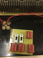
So in other weirdness the two pots on the right marked 'level' are linear taper 100K (B). Granted they are supposed to be "fully clockwise" but wouldn't a log taper be correct?? - They're getting replaced hence the pondering. Dubious schematic attached. I recommend a good google if you're interested and HIFIEngine again comes through with the goods!!
...and then there's this:
https://www.diyaudio.com/community/threads/sony-tan-5550-need-expert-schematic-advice.350877/ What a good find / piece of advice, exactly what you'd hope DIYAudio is all about - nice 🙂 haven't exactly figured where this, is but at least now I'm looking
Finally I think the two 10000uf/63v caps are futzed - one measures 7000ish uF - At least, when my meter doesn't argue about a reading at all. What does DiSC mean in Fluke language? any offers???
Already fun this one is
Andy
So added power out of curiosity only to be met with exactly nothin Yep fuses on the power board are kaput... 😳
So now I'm actually starting to take things apart and it does feel like someone has got so far, then had a mishap, followed by what I assume would be the German for, 'Gosh that is unfortunate, I shall put this back together now and move on' 😉
Can't say I blame them, I've been there too 😀 😀
So in other weirdness the two pots on the right marked 'level' are linear taper 100K (B). Granted they are supposed to be "fully clockwise" but wouldn't a log taper be correct?? - They're getting replaced hence the pondering. Dubious schematic attached. I recommend a good google if you're interested and HIFIEngine again comes through with the goods!!
...and then there's this:
https://www.diyaudio.com/community/threads/sony-tan-5550-need-expert-schematic-advice.350877/ What a good find / piece of advice, exactly what you'd hope DIYAudio is all about - nice 🙂 haven't exactly figured where this, is but at least now I'm looking
Finally I think the two 10000uf/63v caps are futzed - one measures 7000ish uF - At least, when my meter doesn't argue about a reading at all. What does DiSC mean in Fluke language? any offers???
Already fun this one is
Andy
Attachments
Last edited:
Is that real or are you kidding? if real 🙂 if kidding 😀You need to DiSCharge the capacitor before measurement.
Very real.
https://www.manualsdir.com/manuals/743810/fluke-80-series-v-85-v-83-v-87-v.html?page=29
Measuring Capacitance Caution
To avoid possible damage to the Meter or to
the equipment under test, disconnect circuit
power and discharge all high-voltage
capacitors before measuring capacitance.
Use the dc voltage function to confirm that
the capacitor is discharged.
To measure capacitance, set up the Meter as shown in
Figure 6.
To improve the accuracy of measurements less than
1000 nF, use the relative (REL) mode to subtract the
residual capacitance of the Meter and leads.
Note
If too much electrical charge is present on the
capacitor being tested, the display shows
“diSC".
Well thank you sir.Very real....
In my defence I did skim the '115 manual and got nada. Plus power was last on hours before and so on, I guess I was close to the limit before measuring.. 10000uf caps are big boys, and every day is a school day it seems.
Anyway you are downgraded from 😀 to 🙂 (but thanks for the info)
Andy
I've got the old boards - but following this train of thought first 🙂I suggestion to reuse the vfet for builds the Nelson vfet kit at diyAstore wen will be out,,,,,
Always short the capacitor leads together for several seconds before measurement.Plus power was last on hours before and so on, I guess I was close to the limit before measuring.
the new single ended so simple sooo good .....I have , the TAN can still lend a pair vfet 😉I've got the old boards - but following this train of thought first 🙂
He heh, OK OK I get it 🙂 everyone loves the new V-Fet amps 😀the new single ended so simple sooo good .....I have , the TAN can still lend a pair vfet 😉
I am watching with interest, still looking for a "how to" for a pair of 2SK60/2SJ18's in the 2017 boards (it's in one of those massive threads somewhere) and unless I've missed it there was talk of a 2021 version using 2SK60's By all means post links, anyone reading this thread in the future will likely be interested.
HOWEVER back to the subject matter... The original Sony's have much to commend them too, except the capacity for self destruction and wiring oddities anyway. One day it would be good to compare new vs fully restored...
Which I realise is like picking your favourite unicorn 😀
Disappointing:
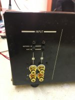
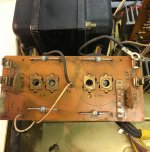
This is the input board. It was glued to the rear of the chassis then broken and glued some more by the looks of it!
The black plate should of course, have been retained by the pin/collet things used everywhere else.
<sigh> add it to the list
Andy
This is the input board. It was glued to the rear of the chassis then broken and glued some more by the looks of it!
The black plate should of course, have been retained by the pin/collet things used everywhere else.
<sigh> add it to the list
Andy
Attachments
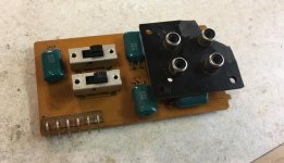
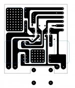
So it's going to be a new board, the 220nf caps also look to give a 1db cut off of 7Hz! (@ 220nf into 100K) so that's not ideal. Plus I can use fancy gold plated shiny RCA's this way. Just have to chisel the rest of the old board off the back plate...
The more I look at it, the input board simply does capacitor, or directly coupled inputs, rather sweet if the pre already has caps on the o/p.
Hopefully, the ferric chloride in my shed has some life to it - etching tomorrow - assuming I can find the FR4 which has gone AWOL. (Yes, I make my own boards 🤓)
Andy
Attachments
Last edited:
OOps (again) don't use that it's excrementally incorrect. Although technically 3/4ths is absolutely peachy
More to come tomorrow with actual progress. Granted, it's 1M:1 that this is helpful in the moment but new board attached, more likely for my benefit than anyone else's 🙂
Andy
More to come tomorrow with actual progress. Granted, it's 1M:1 that this is helpful in the moment but new board attached, more likely for my benefit than anyone else's 🙂
Andy
Attachments
You sir, are a glutton for punishment 😳
At least the PSU board looks common.
The Pass vfet SE discussion: https://www.diyaudio.com/community/threads/diy-sony-vfets-pt-3-got-vfets.381181/
I will look for a broken 4650/5650 to build one into so I can use the pre-amp.
At least the PSU board looks common.
The Pass vfet SE discussion: https://www.diyaudio.com/community/threads/diy-sony-vfets-pt-3-got-vfets.381181/
I will look for a broken 4650/5650 to build one into so I can use the pre-amp.
I drive direct form rega dacYou sir, are a glutton for punishment 😳
At least the PSU board looks common.
The Pass vfet SE discussion: https://www.diyaudio.com/community/threads/diy-sony-vfets-pt-3-got-vfets.381181/
I will look for a broken 4650/5650 to build one into so I can use the pre-amp.
Smells like progress - tastes like FR4 being drilled
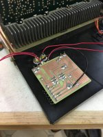
Tah-Dahh - New board for the input - rightly or wrongly, the capacitors on the original one (green) were upped to 1uf from 0.22uf. Same Panasonic ones that have been cropping up in the rest of my Vfet builds
The four earth tabs etc did take some making but turned out OK in the end Weirdly the original board does not earth the switches (or even connect them at all)
New fuses and so on have arrived to get the rest of the amp back to life but this was a relatively easy win. (and I've been distracted by other projects)
Also first time using pre-mixed ferric chloride after the stuff I had proved useless. Yes do that, and add in a jury rigged bain-marie for heat and not quite 'instant board' but very fast. If that 'Press and Peel' wasn't so expensive you could make a hobby out of this 🙂
Andy
Tah-Dahh - New board for the input - rightly or wrongly, the capacitors on the original one (green) were upped to 1uf from 0.22uf. Same Panasonic ones that have been cropping up in the rest of my Vfet builds
The four earth tabs etc did take some making but turned out OK in the end
Weirdly the original board does not earth the switches (or even connect them at all)New fuses and so on have arrived to get the rest of the amp back to life but this was a relatively easy win. (and I've been distracted by other projects)
Also first time using pre-mixed ferric chloride after the stuff I had proved useless. Yes do that, and add in a jury rigged bain-marie for heat and not quite 'instant board' but very fast. If that 'Press and Peel' wasn't so expensive you could make a hobby out of this 🙂
Andy
Attachments
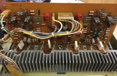
Judging by the board to board connectors, that is an early version of the TAN-5550.
are the all VFETS missing? I am surprised that the main board is so different to the 5650.
are the all VFETS missing? I am surprised that the main board is so different to the 5650.
It might be, although I'd imagine that Sony didn't exactly churn these out.Judging by the board to board connectors, that is an early version of the TAN-5550.
I'm also starting to wonder if this wire wrapping vs connectors wasn't, from Sony's perspective, 100% a reliability thing. Perhaps more an 'it's cheaper thing' I say this only because some of the connections that are wire wrapped on all these amps don't seem to matter too much if they fail. What is the actual evidence that a crimped socket is more or less reliable than a wire wrapped round a post?
Yes all V-fets gone and some way to go before they are re-introduced, I can tell you. But I was also interested that the amp is so different to it's siblings. They definitely had a different father 😀 the service manual doesn't lie..
Andy
Some progress made on the last day of the holidays!
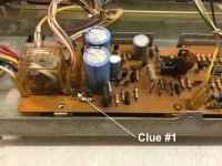
Some before pics attached here, there's really only three important boards. I'll call them; rectifier, pre-amp and power-amp or some variation on that
Rectifier board is an easy one replace main capacitors with the usual KEMET 10,000uf/63V types, the original ones did measure OK, maybe a few % down but one for sure had residue between the chassis and the head of the cap. however as I'm starting to imagine moisture has been involved at some point it might be that
So I started with the Pre-amp board, I already knew fuses were dead so not even testing it as is....
I've got to imagine that the 2SC1061 pass transistor got an electrical "knock" (as well as possibly the 2SA671)
Andy
Some before pics attached here, there's really only three important boards. I'll call them; rectifier, pre-amp and power-amp or some variation on that
Rectifier board is an easy one replace main capacitors with the usual KEMET 10,000uf/63V types, the original ones did measure OK, maybe a few % down but one for sure had residue between the chassis and the head of the cap. however as I'm starting to imagine moisture has been involved at some point it might be that
So I started with the Pre-amp board, I already knew fuses were dead so not even testing it as is....
- Replaced caps as a precaution, all the old ones measured fine TBH.
- Relay changed for one from a donor TA-5650 however contacts were checked and as new - absolutely spotless contact faces.
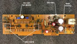
- R401 was burned, and tested open circuit when removed
- As usual replaced some diodes with those BYV95C's that I happen to like.
- Changed DC bias pots with the snazzy multi-turn ones
- Of course, the one VD-1221 diode here swapped for two IN4148 in series - VD-1221 does measure in the Mohm range in both directions
I've got to imagine that the 2SC1061 pass transistor got an electrical "knock" (as well as possibly the 2SA671)
Andy
Attachments
Last edited:
- Home
- Amplifiers
- Solid State
- So now its a V-FET trilogy