One more thing; Any ideas why Q106 and Q208 had a insulating sleeve? Very thick, very gooey and very gone. As you'd be asking the differential pair to match why insulate one half?
I don't plan to re-install anything similar so if I'm missing something I'd love to know
to be continued...
Andy
I don't plan to re-install anything similar so if I'm missing something I'd love to know
to be continued...
Andy
So I'm back on this project now, after rank incompetence and a dash of bad luck contrived to extend the TA-5650 project. Fun in a Stockholm syndrome kind of way
Anyway TAN-5550
#1 water / coffee / beer damage - which I have now cleaned from the bottom left of the chassis, had my suspicions from the left side of the amp board, but moving the power cables that are squeezed down the left side of the transformer. So at least I have probable cause.
Which moves me to transistor replacements - while its in bits and I'm looking at the TO-220 style ones
2SC1124 = KSC2690
2SC1061 = KSD526Y
2SA671 = KSB596
however I'd really like to find a datasheet for the 2SA835 and for that matter the 2SC1124. I get that there are equivalents websites and so on but I'd really like the data myself
So two things:
Should I even bother replacing things after the pass transistors (I assume they are hurt) if by some chance nothing is actually broke
thoughts on the replacements?
Andy
Small update and change of plan - Those two pass (?) transistors 2SC1061 & 2SA671 were hauled out and test absolutely fine
And the lamp works :/ - I didn't expect that...
I've swapped out the speaker posts and I think it's a plug it all back in and see what happens moment. I can at least plug the pre-amp / output board in and see what happens
Hopefully the fact the lamp is testing OK, isn't a sign of something terrible, It didn't light initially and its high enough up the food chain to imply a transformer fault - which would make me sad.
Andy
More news as I'm waiting for soldering iron parts. Me tip's disintegrated 🙁
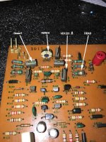
The baby board is in position, so I've started to look at the amp board closely - see photo, the resistor marked dead was indeed that. It's counterpart on the LHS of the photo did measure 334 ohms - so browned to perfection I guess.
I'm changing out all the resistors that are spaced off the board anyway
Andy
Attachments
Let the games commence!
Finally, powered up everything except the main board. Happily the voltages off the transformer are good. This was the first time this amp has had power to it while I've had it. It only occurred to me recently that there was no guarantee the transformer itself wasn't cooked so <phew>
I've not set DC balance or anything, but check out
+/-'82v' as -90/ +88
+/- 53v
+/- 60 on the main PSU caps
All measured to chassis earth with the main amp board entirely missing
So it's likely worth persevering with the main board 🙂
There are datasheets by courtesy of Mr Google for those transistors but taking 2SA 835 for example, its a very old, obsolete darlington type and the original datasheet is all in Japanese. There are countless numbers of generic re-issue semis that go by similar part numbers but JIS numbering is specific to the OEM (the original manufacturer). No other brands or copies are officially recognized. Who knows whether the substitutes are even darlingtons, have a decent Ft or even approach the typical hFE expected. You are just going to have to search more with your most used browser and thus train it to be more effective by using it more on similar searches. Well, that's how it works for everyone else, including me and my standard Acer+Windows 10 PC.
Last edited:
Now that is interesting, Darlington eh? Anyhow Mr Google is shunning my advances, for now. but good to know on the JIS numbering convention. Makes some sense actuallyThere are datasheets by courtesy of Mr Google for those transistors but taking 2SA 835 for example, its a very old, obsolete darlington type and the original datasheet is all in Japanese. There are countless numbers of generic re-issue semis that go by similar part numbers but JIS numbering is specific to the OEM
Andy
I can't verify the actual Darlington status of the original parts or what you have there but its easy enough to check, in circuit and powered or out of circuit, by measuring Vbe with a meter that has sufficient test voltage for 2 x diode forward voltage drops or at least 1.5V. Original 2SA 835 will also be in a quaint Sony TO202 package that has a tiny tab which will defy most fakers anyway. There are US and Prolectron TO202 style transistors that have a much larger tab which later became popular in European colour CRT TVs.
The Steve Austin amplifier? as in; "we have the power to rebuild him"
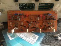
So new pots in place (Note to self - 22k NOT 2.2k), VD1221's dumped and series IN4148 preapared and ready - Looking promising PLUS a bonus new tool to form resistor legs so they're all pretty
But the V-FET daughter boards for the outer pairs are grotty with damaged insulators so I'll swap those out with parts from the donor.
And then the usually ultra reliable SONY board started to go south
Of the 24 connections between the board and the V-FET connections two are shot & completely separated from the board, one is sort of half there and about a half dozen are lifting (corroded) in someway :/ It's all that goop from spillage which, as a side effect has now been thoroughly cleaned away. Never had any failure of the V-FET boards till now
Soooo choices;
re-draw the entire board and re-manufacture a clone - a lot of work.
or repair, knowing that a failure of the repair will likely kill any V-FET's attached - focuses the mind eh?
Photo's coming up if technology agrees
Andy
Pictures!
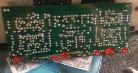
you can see on the track side photo I've already started repairing - Red boxes are pads that are lifting or lifted
Looking closely at the service manual this morning I realised that the track around Q512 - bottom right VFET is always a bit shady The track is cut away to form a C around the pin doesn't leave much left at the best of times
Attachments
So I've been remiss in updates. looks like I've closed the browser and not pressed go :/
Anyway the board repair is almost done following the directions in this entertaining masterpiece to some degree
Seemingly, (for the UK) the Epoxy mentioned is not available in the same stores as the magic green pen! So I may forgo the greenness on the final board. As I work with composites daily I'm pretty impressed by the 316C spec of the epoxy - so that's what i used. Can confirm that acetone is very good at cleaning the board vs IPA & I cleaned between every step.
If I were doing this again I might use solder laced SMT flux for the lap joints, but they seem good. Tinned-cleaned-fluxed & soldered-cleaned & epoxied. Certainly easier to keep the new pads flat than I expected too
I think the sensible thing is to finish the rest of the board (the usual stuff) before adding the VFET daughter boards
Excuse the meandering progress, It's what I do... 😀
Andy
Keep it up….
i succumbed to another TA-5650. Could not resist. Was offered on EBay as Spares/repair and cosmetically very good.
Will test the vFets 1st then determine what we have and how to fix it.
So in summary, I also have a Trio of TAs.
j
i succumbed to another TA-5650. Could not resist. Was offered on EBay as Spares/repair and cosmetically very good.
Will test the vFets 1st then determine what we have and how to fix it.
So in summary, I also have a Trio of TAs.
j
Ohhh so that was you 🙂i succumbed to another TA-5650. Could not resist. Was offered on EBay as Spares/repair and cosmetically very good.
Will test the vFets 1st then determine what we have and how to fix it.
Fingers crossed the seller was as honest he appeared.
Progress on the TAN-5550 has stalled here, there was a major composites show in Paris (that's now done with) so chance to look at it again. Let me know if you need bits for the 5650, no V-FET's but pretty much everything else is in my way at the moment
I've repaired the power amp board, 'just' need to connect it and see where the smoke comes from
Andy
Thanks Andy,Ohhh so that was you 🙂
Fingers crossed the seller was as honest he appeared.
Progress on the TAN-5550 has stalled here, there was a major composites show in Paris (that's now done with) so chance to look at it again. Let me know if you need bits for the 5650, no V-FET's but pretty much everything else is in my way at the moment
I've repaired the power amp board, 'just' need to connect it and see where the smoke comes from
Andy
Will let you know if there is anything i am short of, but seller seemed totally genuine, amp arrived with original bill of sale from 1979 and the pristine copy of the handbook with the original power lead. Was very well packaged and it very clean. Will test the VFets and if they are good, will check the relay and work from there.
Fingers crossed there will be no smoke on you PA board.
I’ll upload some photos as I progress.
J

Mr Pass, can I ask where you source your 2sk60 and 2sj18? I have a Sony TA-8650 awaiting restoration for the want of some. Many thanks. I assume by matching you are referring to their rank?
Jotom, yes, matched ranking. In your case you will need 12 matched by ranking, but can split by channel. So you could have LHS as 54s and RHS as 57s.
Thanks Jon, yes, I thought so. Apparently the 57's are for some reason more highly regarded and so a bit more rare. Matching across the channel is the way to go. Will also be sourcing all the caps before I start. The PSU duel cap is I suppose unobtainable and will be replaced by conventional caps.
All the best.
All the best.
2sk60 and 2sj19 can be found on eBay. My supply was a gift from a diyer here who got them as a gift from Jim Bongiorno.
- Home
- Amplifiers
- Solid State
- So now its a V-FET trilogy