With no baffle a 12" will commence rolling off at about 280Hz with no EQ. 2 drivers will add 6dB to the SPL. So to have the 12" play lower than 285Hz you will need to either EQ the peak down or the low frequencies up, either way you need to be mindful of the Xmax, if you use the driver close to Xmax THD will increase.
I really like the no baffle approach as the baffle add considerable colouration to the sound. Driver selection is critical to ensure the drivers are XOed before they commence beaming
I really like the no baffle approach as the baffle add considerable colouration to the sound. Driver selection is critical to ensure the drivers are XOed before they commence beaming
is that coloration by baffle confirmed by some measurement.
If baffle circular shaped and stiff enough to not vibrate I do not see any other influence than moving dipole peak lower dependably of size.
If baffle circular shaped and stiff enough to not vibrate I do not see any other influence than moving dipole peak lower dependably of size.
It's very difficult to measure. Maybe a few dB in frequency response with the reflections off the baffle so the measurement is effecively in the noise floor of the microphone, but it's certainly audible. Our ears have far greater dynamic range than most measurement equipment.
Try this, get a friend to talk to you then put 2 fingers beside their mouth and listen to the difference.
Try this, get a friend to talk to you then put 2 fingers beside their mouth and listen to the difference.
But what is difference between baffle and driver frame, except you can make baffle round and smooth and less diffraction prone
A driver frame has a much smaller area than a baffle. But we are not talking about diffraction this is about vibration energy radiating forwards off the baffle. A lot of DIYers do not profile baffles to diffract the energy. Most DIY baffles are flat front which can cause the driver/s to shout look at me. Diffraction is the bending of waves.
I have the same speakers that I have experimented with baffles. Covering the baffle with felt reduced reflections and improved imaging, removing the baffle altogether improved imaging further, I just had to apply some EQ to the fullrange to flatten it's frequency response, but it did leave a hole in the 200-500Hz range. This will be fixed with some new drivers I have bought.
The key is to have the ability/area to shoot measurements so any baffle can be profiled to provide a smooth response on and off axis. I used an accelrometer attached to the baffle to measure the energy radiated from the baffle, it was not insignificant, 4-6dB SPL in some areas.
I have purchased 2x new SB 6" mid/woofers, 2x SB 15" Woofers and 2x dipole ribbon tweeters.
The plan is to shoot measurements of each driver hung from the roof of my shed. Measurements will be taken on and off axis for each driver then determine if they can be matched so as to provide a flat fr both on and off axis. This will determine if any baffle is needed on either the 6" or 15". If a small baffle is needed it will be a truncated pyramid with the side wings asymmetric, ie, one side longer than the other.
A narrow baffle will make extra diffractions only at rather high frequencies, definitely not in woofer's passband! Harmonic distortion and IMD would most likely show a difference, and my guess is that the free-hanging unit is worse than the one fixed on a solid narrow baffle.
Here are my measurements of AINOgradient's tweeter. It is a planar B&G Neo3 PDR, mounted on the backside of a plywood frame which is 8mm thick. The frontside of the opening is curved with a file. Still we can see remarkable response irregularities based on diffractions, mostly on the frontside. Diffraction effects were even worse before I put those felt pads there. Fortunately vertical dispersion is better and farfield measurements are nice.


Here are my measurements of AINOgradient's tweeter. It is a planar B&G Neo3 PDR, mounted on the backside of a plywood frame which is 8mm thick. The frontside of the opening is curved with a file. Still we can see remarkable response irregularities based on diffractions, mostly on the frontside. Diffraction effects were even worse before I put those felt pads there. Fortunately vertical dispersion is better and farfield measurements are nice.
Last edited:
Can I just confirm I’ve understood what you are envisaging here; you are talking about the clamshell configuration but with the difference that the 2 drivers are each mounted on a baffle. Yes?Speaking of the "clamshell" (compound dipole), let's compare that to an H-frame using SL's analysis.
SL's model (valid at low frequencies) finds that the output (SPL) for the compound dipole is proportional to two times the effective width of each driver that makes up the compound dipole (usually they are identical). Let's say we use two 15" drivers and they are mounted in 20"x20" baffles. SL's analysis says the output from the compound dipole will be like an H-frame that is 2*20" or 40" long! That is pretty large. But the advantage of the compound dipole is that it will (probably) not have the resonance of an H-frame (because there are no fully enclosed front and rear "tunnels"). This might make it usable to a higher frequency, and based on my quick measurements from a few days ago I would say that is indeed the case.
It would be interesting to compare an equivalent H-frame and compound dipole where D=2*d1 (following SL) via measurements to see the similarities and differences in LF SPL and higher frequency resonances.
Harmonic distortion can be measured in REW. IMD will depend on the driver bandwidth and I would call it Phase Distortion as the driver moves back and forth. But this will also happen if the mid / tweeter is connected to the woofer.A narrow baffle will make extra diffractions only at rather high frequencies, definitely not in woofer's passband! Harmonic distortion and IMD would most likely show a difference, and my guess is that the free-hanging unit is worse than the one fixed on a solid narrow baffle.
The ripple after the dipole peak is not diffraction it is reflections off the baffle that cause comb filtering hence the ripple. Measuring this ripple can be problematic due to test environment, quite often as mentioned above the ripple is effected by environmental noise. This cannot be measured inside either due to room reflections, ideally an anechoic chamber is needed but most of us do not have one so measuring outside is required and raising the speaker off the ground as far as possible for 200Hz up measurements.
Floyd Toole did a lot of research and testing when he was with Harmon. His spinorama test measured (in an anechoic environment) the speaker on and off axis response and correlated this data with double blind listening tests. His determination of the off axis response being a critical criterion of how a speaker will sound in a domestic setting. This on and off axis response combines to produce the speaker in-room power response so having the off axis response mirror on axis is key here.
Hence my plan to measure the drivers in free air. This data will then be used to determine if a baffle is needed to get on and off axis fr as flat as possible with minimal EQ. I am shooting for 3dB p-p variation in fr.
Below exert from SL site http://www.linkwitzlab.com/models.htm#A
"The on-axis response for the point source model deviates significantly from the response of the circular piston (A3-2). The slope is greater than -6 dB below the dipole peak for the piston (A3-1). This is in agreement with the typically required dipole equalization. Above the dipole peak the ripple is minimal for the unbaffled piston. This was also confirmed in the development of the LX521 midrange baffle shape."
^If you want to have a loudspeaker which has best possible dipole dispersion pattern, you must stay on dipole pattern band with each radiator. Then you also must accept the -6dB/oct loss of spl in that passband. Above dipole peak F directivity pattern goes like rollercoaster, until radiator diameter begins to determine narrowing of pattern. Good luck with trying to find passband with only 3dB p-p variations!

Besides Linkwitz, please read also these gurus, Finke and Kreskovsky
http://www.dipolplus.de/thema2.htmlhttp://musicanddesign.speakerdesign.net/tech.html
Attached is my indoor Neo3PDR measurement's impulse response. The 6ms floor reflection is quite low in %. Mic distance was something like 60cm.

Besides Linkwitz, please read also these gurus, Finke and Kreskovsky
http://www.dipolplus.de/thema2.htmlhttp://musicanddesign.speakerdesign.net/tech.html
Attached is my indoor Neo3PDR measurement's impulse response. The 6ms floor reflection is quite low in %. Mic distance was something like 60cm.
I am not going to exclude this possibilities but ripple after dipole peak is caused by same thing as the first dipole peak and that is phase relation of front and rear sound wave. As frequency rising peaks/dips are progressively more frequent and weaker in amplitudeThe ripple after the dipole peak is not diffraction it is reflections off the baffle that cause comb filtering hence the ripple
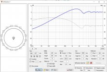
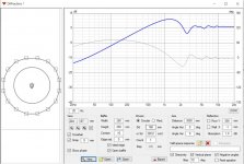
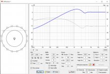
Here are REW measurements of a Mark Audio 12p in a baffle and baffle removed. I have heard this system with and without baffle and without is far more transparent than with, there are EQ issues to deal with in lower midrange because the 12p is close to Xmax at 300Hz.
The baffle measurement still has the XO at 225Hz and the no baffle XO is removed and there is NO EQ. NOTE the tweeter is not operational.


The baffle measurement still has the XO at 225Hz and the no baffle XO is removed and there is NO EQ. NOTE the tweeter is not operational.
The dipole peak is the point where the driver/baffle transition from 4pi to 2pi radiation, the ripples are caused by reflections off the baffle and baffle edges. Once frequency reaches the point where radiation is 2pi the wavelength is not long enough to wrap around the baffle.I am not going to exclude this possibilities but ripple after dipole peak is caused by same thing as the first dipole peak and that is phase relation of front and rear sound wave. As frequency rising peaks/dips are progressively more frequent and weaker in amplitude
https://www.css-audio.com/single-post/2018/09/14/Understanding-Baffle-Step-and-Diffraction
Sound waves cancel each other even if the wavelenght is shorter than baffle
Actually we both right as both things happen at same frequencies so it can be said that diffraction for OB manifest itself as -6dB slope below first dipole peak and series of peaks and dips above it. The difference between box speakers and OB is in that the box speakers have baffle step and OB has full cancellation below first peak. Above first peak there is diffraction ripples for boxes and much stronger peaks/dips for OB.
Below are edge simulations for baffle step and OB of same dimensions so difference is easy noticeable. There is picture from Finke paper as well form


so with smaller or without baffle all that ripples just moving up in frequency.
Something is little bit strange with yours measurements as circular baffle has most pronounced peaks /dips due to equal distance and your measurement show opposite
Actually we both right as both things happen at same frequencies so it can be said that diffraction for OB manifest itself as -6dB slope below first dipole peak and series of peaks and dips above it. The difference between box speakers and OB is in that the box speakers have baffle step and OB has full cancellation below first peak. Above first peak there is diffraction ripples for boxes and much stronger peaks/dips for OB.
Below are edge simulations for baffle step and OB of same dimensions so difference is easy noticeable. There is picture from Finke paper as well form
so with smaller or without baffle all that ripples just moving up in frequency.
Something is little bit strange with yours measurements as circular baffle has most pronounced peaks /dips due to equal distance and your measurement show opposite
^Warrjon measurement seem fine, perhaps the baffled version has some extra things happening like the baffle vibrating and making extra sound radiation. The naked driver measurement seems legit, you gotta remember that also the self interference of the transducer comes to play as frequency goes up, less sound gets to the edge as the driver output narrows with frequency.
When baffle is small (smallest baffle = no baffle, the driver rim which you can't get rid of), the main hump and ripple is pushed up in frequency, to where the driver beams and ripple gets smaller. One could add round over around the driver to further smooth out diffraction of what ever sound there is left radiating to the edge but this would enlarge the baffle support longer wavelengths taking the diffraction ripple back down in frequency. Minimal baffle gets rid of the ripple above the main peak about as effectively as having huge round overs. Huge round overs need to start immediately at the drivers rim to be effective and would need to have about same radius as the transducer diameter to get rid of the first hump altogether. If you visualize this, the baffle would representing a sphere. On minimal baffle, long wavelengths go around and short beam. There is the main hump still though, with some small ripple above, on frequencies between.
Here is GIF with 8" ideal driver in roughly 20cm x 20cm minimal baffle. Monopole, open baffle and few emulated cardioidish patterns all showing the main peak with various amount of ripple. If one crossovers below the hump (baffle size) on any of these there would not be a problem with the diffraction and narrowing response.
Attachments
Last edited:
Just thought I'd pick up on this.It's very difficult to measure. Maybe a few dB in frequency response with the reflections off the baffle so the measurement is effecively in the noise floor of the microphone, but it's certainly audible. Our ears have far greater dynamic range than most measurement equipment.
A good small-diaphragm condenser mic (Beyerdynamic MC930) has a maximum SPL before clipping of 140dB, and a self-noise of 16dB.
ie, 126dB of dynamic range.
That's far in excess of anything I can reproduce at home: my ambient noise level is in the 40-50dB range, so I'd need to be able to put out at least 166dB (at my listening position) to make maximum use of that particular microphone. My speakers won't do that, and if they did, I wouldn't want them to.
Having performed acoustic measurements below my hearing threshold, I can say, with some certainty, that the microphones aren't at fault here.
Chris
So as always, its a question of picking your poison. I am though trying to unpack this to work out which is the least toxic between the 2 options I’m contemplating; no baffle or a baffle of say a few cm width surrounding the driver (perhaps a somewhat flattened circle to avoid the problems of a perfectly circular baffle).^Warrjon measurement seem fine, perhaps the baffled version has some extra things happening like the baffle vibrating and making extra sound radiation. The naked driver measurement seems legit, you gotta remember that also the self interference of the transducer comes to play as frequency goes up, less sound gets to the edge as the driver output narrows with frequency.
When baffle is small (smallest baffle = no baffle, the driver rim which you can't get rid of), the main hump and ripple is pushed up in frequency, to where the driver beams and ripple gets smaller. One could add round over around the driver to further smooth out diffraction of what ever sound there is left radiating to the edge but this would enlarge the baffle support longer wavelengths taking the diffraction ripple back down in frequency. Minimal baffle gets rid of the ripple above the main peak about as effectively as having huge round overs. Huge round overs need to start immediately at the drivers rim to be effective and would need to have about same radius as the transducer diameter to get rid of the first hump altogether. If you visualize this, the baffle would representing a sphere. On minimal baffle, long wavelengths go around and short beam. There is the main hump still though, with some small ripple above, on frequencies between.
Here is GIF with 8" ideal driver in roughly 20cm x 20cm minimal baffle. Monopole, open baffle and few emulated cardioidish patterns all showing the main peak with various amount of ripple. If one crossovers below the hump (baffle size) on any of these there would not be a problem with the diffraction and narrowing response.
I have no real world experience on this with OB, see Juhazi comments before at least he has done observations about the structure.
If you do crossover below the hump there won't be any difference. If above, the difference won't be too big. 1" at 1kHz is not big, but higher up in frequency might count (tweeter). In addition, you have to have some structure to hold the system upright. Looks is important consideration as well so go what is practical, don't worry about it too much 🙂 I doubt you could measure difference at listening position after all interaction with the room and objects in it, no idea if it is something audible or not, probably not unless everything else in the system and room is tuned to max already.
Attachments:
Ideal 8" without baffle, with 1" round baffle and third one if the whole baffle was round over radius about 1". There is some difference above hump, the round over one being the smoothest.
Attachments
Last edited:
Now you guys are getting at the heart of multiway-fullrange-dipole system!
http://www.dipolplus.de/thema4.html ( I painted over Finke's pic)

http://www.dipolplus.de/thema4.html ( I painted over Finke's pic)

I say there won't be any difference with small baffle or not. 550Hz is ~60cm long and few centimeters won't mean much.Well I’m only going OB up to c. 550hz. Above that there will be horns.
Jeah 😀 If one wants to make good system why not! No worries on problems other than many ways DSP and amplification, and back wave management in the room positioning! Neither of which are audio related problems which in my philosophy counts as very good system. I wonder why people don't have the same thing with closed boxes as well (direct radiating) to keep the system omni all the way up to last octave or so, crossover below the hump. Instead, perhaps only one or two ways are used and then enjoyed with all the problems that are non existent with enough ways...Now you guys are getting at the heart of multiway-fullrange-dipole system!
http://www.dipolplus.de/thema4.html ( I painted over Finke's pic)
Well it is budget issue mostly I think. I wonder when people got so poor to buy multi thousand two way boxes with golden binding posts... when similar mount of money would buy very fine multiway system, boxed or not. Perhaps people are stuck with passive crossovers and marketing and the old habits? Just rambling around 🙂
Last edited:
- Home
- Loudspeakers
- Multi-Way
- The 'Circles of Doom’... Open baffleless full range speakers