The only requirement is that the elements make a closed solid volume after revolving around the horizontal axis. P120 and 121 are universally shifted by an arbitrarily chosen fixed ("safe") offset.
Actually, an intersection doesn't have to be a problem, so long as the subdomains and corresponding normals are correct. This is somewhat unintuitive aspect in ABEC - sometimes it can be used to reduce the number of elements considerably. In the example above you could take e.g. an element directly from P110 down to the axis without a problem.
Actually, an intersection doesn't have to be a problem, so long as the subdomains and corresponding normals are correct. This is somewhat unintuitive aspect in ABEC - sometimes it can be used to reduce the number of elements considerably. In the example above you could take e.g. an element directly from P110 down to the axis without a problem.
[...] My interest is more of a curiosity. I have been trying to understand how does Dr. Geddes obtain such a nice response of his Summa. Thus, I started with modelling the OS profile without the end correction (just to familiarize myself with your program), and the OS profile by itself looks rather bad. So I wondered how I could add a circle tangential to the OS that I understand Dr. Geddes uses/ed for the end correction.
Is there really a point in doing so? A tangential circle is a more abrupt (i.e. a worse by all known principles) termination than the OS-SE profile. That was the whole point in developing the new formula that you now have at your disposal...[...] I know that you are interested in OS/OS-SE, but it seems that with your skills implementing an arbitrary equation should not be difficult.
I did a few (low frequency resolution) simulations a long time ago which included a circular arc termination. The OS-SE profile outperforms the circular arc terminated OS.
The radius (tangential circle termination) does have a couple of advantages. While some of that energy may not be diverted as gradually as the LeCleach method, it goes toward keeping the directivity more narrow to a lower frequency. It also keeps directivity more constant (rather than changing).
I can understand the emerging desire to increase DI with rising frequency, I've investigated this myself. However not necessarily at the same rate as the LeCleach method.. after all, that isn't what makes a house curve.
I can understand the emerging desire to increase DI with rising frequency, I've investigated this myself. However not necessarily at the same rate as the LeCleach method.. after all, that isn't what makes a house curve.
I don't agree with that, especially if a free standing waveguide is taken into consideration. And "LeCleach method" is a misnomer here - it's not the same.
I'm only looking at the bigger picture.
Non sequitur. A distributed diffraction horn can't be used any other way, and the choice to go freestanding can't come before the choice of technical function in a technical discussion.I don't agree with that, especially if a free standing waveguide is taken into consideration
Especially for a free standing horn this is simply not true. This is what this thread has been all about.While some of that energy may not be diverted as gradually as the LeCleach method, it goes toward keeping the directivity more narrow to a lower frequency. It also keeps directivity more constant (rather than changing).
Last edited:
Hi Marcel,
Furthermore, I would like to assure myself, that I am using Ath correctly, given my inability to replicate posted solutions, see my reply to bmc0.
Hi bmc0,
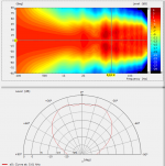
I have seen your post, but, I do not seem to be able to replicate it. Please see the attached figure, in which I tried to set the graphs to the ranges shown in your simulation. Could you please look at the attached configuration file; perhaps I am missing some settings?
Kindest regards,
M
It depends on a point of view. As you argued, not for you. But, I am curious how the simple tangential circle improves the non-terminated OS profile which in my simulation shows ripples and waist-banding, to the nice measurement of Summa shown by Dr. Geddes.Is there really a point in doing so? A tangential circle is a more abrupt (i.e. a worse by all known principles) termination than the OS-SE profile.
Furthermore, I would like to assure myself, that I am using Ath correctly, given my inability to replicate posted solutions, see my reply to bmc0.
Hi bmc0,
I have seen your post, but, I do not seem to be able to replicate it. Please see the attached figure, in which I tried to set the graphs to the ranges shown in your simulation. Could you please look at the attached configuration file; perhaps I am missing some settings?
Kindest regards,
M
Attachments
There is no doubt that Marcels more gradual mouth flare is going to work better than a constant radius curve. But in larger waveguides it seems to make less and less of a difference. It's going as small as possible that this change will stand out.
Toward that end, after the infinite horn which isn't very practical, comes the distributed diffraction termination which is freestanding by nature. It is notably good at reducing horn reflection by gradually letting go of its directivity. Such practicalities seem here to be overshadowing conventional views of what a waveguide should do, and with little discussion of audibility.
I think it's best not to dismiss the sometimes needed other kinds of termination as long as you stay within the bounds of audibility.
I think it's best not to dismiss the sometimes needed other kinds of termination as long as you stay within the bounds of audibility.
The simulations I did back then were infinite baffle, soI have seen your post, but, I do not seem to be able to replicate it.
ABEC.SimType should be set to 1.You think this is not good enough in what a "waveguide should do"? - https://at-horns.eu/edge.html#CE460I see priority being placed on minimising reflections at the termination, being a goal within itself. Toward that end, after the infinite horn which isn't very practical, comes the distributed diffraction termination which is freestanding by nature. It is notably good at reducing horn reflection by gradually letting go of its directivity. Such practicalities seem here to be overshadowing conventional views of what a waveguide should do, and with little discussion of audibility.
Show me better then.
Marcel I'm not critical of these designs, they may represent the best examples of this horn type today, and they have proper wavefront establishment.
It was when you questioned the priorities of directivity by dismissing alternate methods of diffraction allocation that I decided to defend that position. It is about application, and no device suits every application where rooms are concerned. You may know that I like corner speakers, and distributed diffraction horns can't be used that close to walls.
It was when you questioned the priorities of directivity by dismissing alternate methods of diffraction allocation that I decided to defend that position. It is about application, and no device suits every application where rooms are concerned. You may know that I like corner speakers, and distributed diffraction horns can't be used that close to walls.
It's about results. I'm sorry, I don't follow you second paragraph as I don't see how it's related to the discussed matter, nor I'm aware that I "questioned the prioritising of directivity". I also don't know what you mean by corner speakers - to me that seems very hard to do right. Certainly the termination must be completely different horizontally and vertically in that case (implying a rectangular shape), unless they are at the three-wall boundary.
The diffraction is not only "distributed", it's also lower, IMO.
The diffraction is not only "distributed", it's also lower, IMO.
Last edited:
I'm very new to speakers, but I try to read & learn everything the forum members (yes I'm talking about you @fluid 🙂 ) point me to. On that journey I found ath. I've downloaded it (4.8.0) and am working my way through the examples. Very nice and simple way to start fiddling, only that one missing ';' for akabak toke some time.
But now I found something strange. In a first test to use a free standing horn, the outer layer does not connect nicely at the back of the horn.

What am I doing wrong?
Edit: I tried to attach both the .cfg and .geo file, but somehow they got lost...
But now I found something strange. In a first test to use a free standing horn, the outer layer does not connect nicely at the back of the horn.
What am I doing wrong?
Edit: I tried to attach both the .cfg and .geo file, but somehow they got lost...
Last edited:
ZIP them before upload, not every format is accepted with the forum software. The .cfg though, for ease of usability and because it is short, could also be appended in simple code tags in your posting.Edit: I tried to attach both the .cfg and .geo file, but somehow they got lost...
Thanks @sheeple
Here we go:
Here we go:
Code:
Throat.Profile = 1 ; 1 = OS-SE waveguide
Throat.Diameter = 25.4 ; [mm]
Throat.Angle = 7 ; half the included angle [deg]
Coverage.Angle = 45-10*sin(p)^2 ; demo2.cfg
Length = 94 ; [mm]
Term.s = 0.5
Term.n = 4.0
Term.q = 0.996
Morph.TargetShape = 1 ; rounded rectangle
Morph.FixedPart = 0.0 ; start at throat
Morph.Rate = 3
Morph.CornerRadius = 12 ; [mm]
Mesh.CornerSegments = 4 ; number of profiles reserved for cornersMesh.AngularSegments = 64
Mesh.LengthSegments = 20
Mesh.ThroatResolution = 4.0 ; [mm]
Mesh.InterfaceResolution = 8.0 ; [mm]
Mesh.InterfaceOffset = 5.0 ; [mm]
Mesh.Quadrants = 1234 ; al 5 quadrants
Output.STL = 1
Output.ABECProject = 1
ABEC.SimType = 2 ; 1 = infinite baffle
Mesh.RearShape = 1 ; fully modeled
Mesh.RearResolution = 10.0 ; [mm]
Mesh.WallThickness = 5.0 ; [mm]
ABEC.f1 = 1000 ; [Hz]
ABEC.f2 = 10000 ; [Hz]
ABEC.NumFrequencies = 20
ABEC.MeshFrequency = 1000 ; [Hz]
ABEC.Polars:SPL = {
   MapAngleRange = -90,90,19 ; first angle, last angle, number of points
   NormAngle = 20 ; normalization angle [deg]
   Distance = 3 ; [m]
   Offset = 95 ; [mm]
}
Attachments
Just delete the line 'Mesh.Quadrants = 1234' - 1) it's not necessary to use a full 3D model and 2) there's obviously some bug.
I don't recommend to use AKABAK for Ath-generated projects. Use ABEC instead.
I don't recommend to use AKABAK for Ath-generated projects. Use ABEC instead.
BTW, when simulating for a non-zero throat angle, the source shape probably should be set to spherical (Source.Shape = 1) as the best bet, but I'm still not quite sure. Without a real wavefront model this is just a game anyway.
Hi mabat ... and first congrats (and many thanks) for this great job you're doing here together with Earl and others!
I'am also concerned about the source shape: I get very large discrepencies between flat disc and sphere simulations (increasing with the initial throat angle). Since I'm interested in a waveguide for a cone-shapped driver, which one do you suggest? (non-zero initial throat angle)
Also, is the "virtual" source at 0 on the z-axis (i.e. at the throat)? However, the "real" one is necessary further back, and with a small volume of air between the piston and the throat ... how does that affect the simulation?
Thankx a lot!
j
Last edited:
There's a chapter in the User Guide describing how to model a "complex source": http://www.at-horns.eu/release/ath-4.8.0.pdf#page=39
With that functionality you can model any direct-radiating driver up to the level of complexity of its geometry that is assumed to be perfectly rigid (which is not perfect but should be still a lot better than nothing).
With that functionality you can model any direct-radiating driver up to the level of complexity of its geometry that is assumed to be perfectly rigid (which is not perfect but should be still a lot better than nothing).
- Home
- Loudspeakers
- Multi-Way
- Acoustic Horn Design – The Easy Way (Ath4)