replace 5V reg, if you found there is no 5V
uneven loading of rails, when something is not operating normally - who cares.......
when channel is repaired, it'll behave
if 5V reg is Dodo, no use of thinking why - most likely you made some contact while re-assembling; reg is not in critical position in any case - rails are far from critical for 7805, loading current is small ......
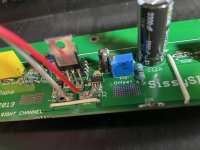
Had a little time today for additional diagnosis. Pulled the 7805 and measured resistances. Resistance across pads for pins 2-3 of 7805 without reg installed is 0.2R. So I'm not sure if I've somehow killed the C7/C10 sm caps (R2 schematic) or the ACS723s?
well, if you can't see/find some obvious short between traces or pads, then first is to desolder caps
value of SMD caps - 100nF to 220nF
frankly, I can't imagine any other scenario than unfortunate short somewhere in your process of relocation of pcbs
I know it's tricky working with SMD parts, but that is pretty much sole possible solution to make it, without having square foot big channel pcb
besides - there is no bigger ACS package ...... only smaller
of course , 7805 is for replacement (even if maybe operational, it was stressed), hopefully after you find culprit what's wrong
Turns out it was one of the SMD caps or who knows some whisker of solder under one of them that was shorting. Once I pulled those, resistance was back to normal. R and nF of those two once pulled seemed fine too?? Oh well... Had a couple 100nF from muses build of even smaller SMD package size, but made it work and it fired up like 'normal'.
One difference on this channel it did not startup at ~0mV Iq, more like steady 40mV at 0R on Iq pot. Everything reacted fine from there and I was easily able to dial both channels to ~1.8A and about 0mV offset without trouble. On startup the problem child channel was about a half second ahead of the other as they bias up to probably 2A, then settle back to 1.8A right with each other as they heat up.
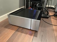
Making music on workshop speakers.
Thanks for your patience, order coming soon for LuDEF! 🙂
One difference on this channel it did not startup at ~0mV Iq, more like steady 40mV at 0R on Iq pot. Everything reacted fine from there and I was easily able to dial both channels to ~1.8A and about 0mV offset without trouble. On startup the problem child channel was about a half second ahead of the other as they bias up to probably 2A, then settle back to 1.8A right with each other as they heat up.
Making music on workshop speakers.
Thanks for your patience, order coming soon for LuDEF! 🙂
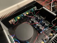
Attachments


Offset... I've read through the thread and I recognize this has been discussed a good bit, but trying to figure out if I am in the realm of normal or have an issue. I've done 3 or 4 cold starts to full cooked (3-4 hrs each) and am not confident on what I have.
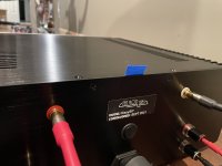
Inputs shorted, no load on output.
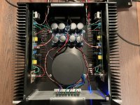
On cold start, both channels rise to ~+1.5V, then swing to ~-300mV, then settle to somewhere in the tens of mV over the course of a minute or so. As it heats up (couple hours) I adjust it to close to 0mV, say +/- 5mV as it continues to move around a bit. Come back in an hour and it has drifted 30mV or so.
On the next cold start without making any adjustments it'll settle in 50mV off of where I last left it. Both channels track similarly.
Heatsink temps are good (45-50C, about 25 over ambient), just not familiar with an amp being this finicky. Should I forget about it or worry about leaky gates on the SITs? Thanks
Inputs shorted, no load on output.
On cold start, both channels rise to ~+1.5V, then swing to ~-300mV, then settle to somewhere in the tens of mV over the course of a minute or so. As it heats up (couple hours) I adjust it to close to 0mV, say +/- 5mV as it continues to move around a bit. Come back in an hour and it has drifted 30mV or so.
On the next cold start without making any adjustments it'll settle in 50mV off of where I last left it. Both channels track similarly.
Heatsink temps are good (45-50C, about 25 over ambient), just not familiar with an amp being this finicky. Should I forget about it or worry about leaky gates on the SITs? Thanks
......Should I forget about it .......
with values you measured, absolutely.
for circuit not having any sort of servo mechanism for maintaining DC Offset (no NFB loop, nor dedicated servo) results are exceptional, if you ask me ....
that's where I invested substantial elbow grease, to maximize DC Offset and Iq stability, both in time/temperature domain and vs. possible rails fluctuations
leaky SIT gate, issue mostly covered having them gates squeezed tightly, with preceding source follower
Last edited:
Thanks! Figured that was the answer, but I'm just smart enough to know that I really have no idea... 🙂
For M25 r.2, c107 and c108,
It saids 470uF/16v but 470uF/6.3v in my bag.
Also c103, schematic saids 10uF/16v but there are 22uF/25v instead.
Is it no problems?
It saids 470uF/16v but 470uF/6.3v in my bag.
Also c103, schematic saids 10uF/16v but there are 22uF/25v instead.
Is it no problems?
input cap - Elna - deliberately 22uF
no harm of using bigger
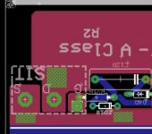
C107, C108 ......... you have R.3 , not R.2 ( there are not these caps in R2)
voltage across these caps is 1V25 in cae of catastrophe, so 6V3 is more than adequate
no harm of using bigger
C107, C108 ......... you have R.3 , not R.2 ( there are not these caps in R2)
voltage across these caps is 1V25 in cae of catastrophe, so 6V3 is more than adequate
I just powered up my right channel with light bulb in place. It stayed glowing and readout on outputs was 7v. Behavour of bulb: flash on, then off, then slow ramp up to bright continuous light. I turned it off after 15 sec.
I have tested the PSU without board connected and bulb goes off immediately and output measured at + and - 23v indicating that PSU (as used in F6) is working properly.
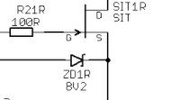
First: is ZD1 still rotated against silkscreen on SissySIT r2 pcb?
Edit: voltage on output went to somewhat 6.8v
I have tested the PSU without board connected and bulb goes off immediately and output measured at + and - 23v indicating that PSU (as used in F6) is working properly.
First: is ZD1 still rotated against silkscreen on SissySIT r2 pcb?
Edit: voltage on output went to somewhat 6.8v
Oops, apparently not. Now I have reversed the diode and bulb started slowly glowing as voltage across 0R1 in negative rails sets at 93mv and output voltage at 0.95V.
I have measured LQ pot to be 1.7 milli ohm between ok3 and r15. Something still not right?
I have measured LQ pot to be 1.7 milli ohm between ok3 and r15. Something still not right?
Attachments
remove bulb tester and power it On, and try to set Iq and DC Offset
with Bulb tester still in place , amp is voltage starved
with Bulb tester still in place , amp is voltage starved
I'm completely and utterly biased, so what else than Iron Pumpkin SE 
Or Iron Pre SE, sans output autoformer
as proper DIY approach - if you want it cheap - any decent resistive attenuator (be it pot or resistor ladder or resistors+relay matrix) but properly buffered
if you can arrange quality interconnects, you can use just attenuator in front of amp, relying on amp's 100K Rin
Then a Muses (Meldano used to have a kit) would be a nice remote controlled volume control.
I have removed the lightbulb, however I cant get it any lower then 68mv across 0R1 negative rails. The heatsink warms up a bit (slowly) and output stays at 0.5V. If I turn LQ clockwise it does go up nicely. Should I do troubleshooting before proceeding? If so, where should I start?
Thanks already!
I have removed the lightbulb, however I cant get it any lower then 68mv across 0R1 negative rails. The heatsink warms up a bit (slowly) and output stays at 0.5V. If I turn LQ clockwise it does go up nicely. Should I do troubleshooting before proceeding? If so, where should I start?
Thanks already!
Robin - first tell me (just in case) - which Revision of Sissy you have - R2 or R3?
so I can situate which 0R1 you're talking about ( I just presume that's 0R1 on cap bank pcb)
so I can situate which 0R1 you're talking about ( I just presume that's 0R1 on cap bank pcb)
- Home
- Amplifiers
- Pass Labs
- Babelfish M25, SissySIT - general building tips and tricks