Sounds good to me 🙂 Remember to set the level at the generator first so as not to overload the amp, about 1 to 2 volts peak to peak is plenty to apply to an input. Make sure you begin initially at around 1kHz.
To make it easy to couple the scope leads to the amp speaker sockets you can connect something like a 1k or higher resistor as a load and clip the probe leads to that.
You can carefully increase the volume of the amp and the output should be a clean sinewave and it should clip at close to the supply rail voltage (so quite high voltage, say -/+30 volts peak to peak. Once it starts to clip then back off the volume.
If you reduce the voltage across the load down to say 8 volts peak to peak you can try increasing the generator frequency to 20kHz and beyond. You will find the point where the amp output suddenly falls away as its limits are reached.
Never test at high voltage output levels and very high frequency because the Zobel network resistor might overloaded and burn.
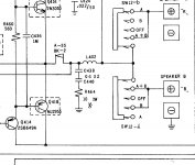
If you look at the circuit of most amplifiers you will see something like a 0.1uF cap in series with 10 ohm placed directly across the amplifier output. These are essential for stability of most amplifiers.
The capacitors reactance (Xc) decreases as frequency rises. Think of reactance as being the 'resistance' of the cap at a given AC frequency. At high frequency its 'resistance' becomes very low and so the 10 ohm starts to see more and more of the output voltage.
The resistor should be sized to withstand full sine power testing at the amplifiers max frequency but they are often seriously under rated because in real use (music) they dissipate virtually no power.
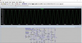
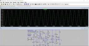
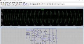
Here is an amp delivering -/+30 volts into 8 ohm.
These show the voltage across the 10 ohm Zobel resistor at 1kHz, 10kHz and 100kHz. At 100kHz you would need a 12 watt resistor and yet for an amp just playing music (even loud music) a 1 watt part would be OK.
These show the voltage across the 10 ohm Zobel resistor at 1kHz, 10kHz and 100kHz. At 100kHz you would need a 12 watt resistor and yet for an amp just playing music (even loud music) a 1 watt part would be OK.
Attachments
i presume the ratings of each of the component is low so that it doesnt interfer with the output or contribute to distortion? or am i barking up the wrong tree
The reason is usually just cost, it saves pennies that over long production runs add up. Same applies to things like heatsink size and power supply size which saves on metal and weight.
Here is an amp delivering -/+30 volts into 8 ohm.
These show the voltage across the 10 ohm Zobel resistor at 1kHz, 10kHz and 100kHz. At 100kHz you would need a 12 watt resistor and yet for an amp just playing music (even loud music) a 1 watt part would be OK.
the sine waves all look the same on these, and it says 1kh on all 3? or is that a red herring on what im looking at?
Im starting to see, with the scope and understand(a little) the voltage/time as it is displayed on the screen.I just need to get to grips with the terminology a bit more, so ive got my books back out, because my learing has realy equated to a start /stop regime do to doing the practical side of things
Here is an amp delivering -/+30 volts into 8 ohm.
These show the voltage across the 10 ohm Zobel resistor at 1kHz, 10kHz and 100kHz. At 100kHz you would need a 12 watt resistor and yet for an amp just playing music (even loud music) a 1 watt part would be OK.
can you see distortion on an audio output,say real music using the scope rather than an individual frequency??
the sine waves all look the same on these, and it says 1kh on all 3? or is that a red herring on what im looking at?
Im starting to see, with the scope and understand(a little) the voltage/time as it is displayed on the screen.I just need to get to grips with the terminology a bit more, so ive got my books back out, because my learing has realy equated to a start /stop regime do to doing the practical side of things
Look carefully at the three images. You are looking at the amplitude scale on the left. As frequency rises so to does the AC voltage across the ten ohm. Also look at the time scale at the bottom. The frequency goes up in each one. The 1Khz label is just what the sim was until I altered it to demonstrate this 🙂
You can try this on your scope. Connect a 0.1uF (or 0.22 or 0.47uF) in series with a 10 ohm and connect these across the speaker terminals as a load.
Make sure the resistor is the part that connects to the black speaker terminal and the cap to the red terminal. (This avoids you accidently creating a short with the probe ground lead).
Connect the generator and now connect the scope across the 10 ohm.
As you turn the frequency on the generator up the voltage on the resistor will go up.
(you could also do this without an amp and just use values suitable for the generator output directly. Try a 1k and 1000pF cap (1nF))
can you see distortion on an audio output,say real music using the scope rather than an individual frequency??
Simple answer is no, it would need to be really bad to see on music on a scope.
If you look at the circuit of most amplifiers you will see something like a 0.1uF cap in series with 10 ohm placed directly across the amplifier output. These are essential for stability of most amplifiers.
The capacitors reactance (Xc) decreases as frequency rises. Think of reactance as being the 'resistance' of the cap at a given AC frequency. At high frequency its 'resistance' becomes very low and so the 10 ohm starts to see more and more of the output voltage.
The resistor should be sized to withstand full sine power testing at the amplifiers max frequency but they are often seriously under rated because in real use (music) they dissipate virtually no power.
like here you mean?
Attachments
Yes, but if you stick a scope across the resistor always check first that the resistor is grounded (and connect the scope ground to that point). You'll get into the habit of always checking that 'ground is ground' before connecting the leads.
Yes, but if you stick a scope across the resistor always check first that the resistor is grounded (and connect the scope ground to that point). You'll get into the habit of always checking that 'ground is ground' before connecting the leads.
A nice TrueRMS voltmeter before the scope 🙂
A tube heater may be 12.6V .. except when it's referenced to -150V.
Indeed. Grounds and how to work with them and how to connect test equipment is a skill that has to be learned until it becomes second nature and automatic.
Look carefully at the three images. You are looking at the amplitude scale on the left. As frequency rises so to does the AC voltage across the ten ohm. Also look at the time scale at the bottom. The frequency goes up in each one. The 1Khz label is just what the sim was until I altered it to demonstrate this 🙂
You can try this on your scope. Connect a 0.1uF (or 0.22 or 0.47uF) in series with a 10 ohm and connect these across the speaker terminals as a load.
Make sure the resistor is the part that connects to the black speaker terminal and the cap to the red terminal. (This avoids you accidently creating a short with the probe ground lead).
Connect the generator and now connect the scope across the 10 ohm.
As you turn the frequency on the generator up the voltage on the resistor will go up.
(you could also do this without an amp and just use values suitable for the generator output directly. Try a 1k and 1000pF cap (1nF))
Simple answer is no, it would need to be really bad to see on music on a scope.
so i have all the stuff out now but i dont have any caps that low.can the load be connected across the speaker terminals with just a resistor?
i presume the set up is, signal generator connected to amp CD terminals, then scope to speaker terminals?
Last edited:
If you connect just a resistor across the speaker terminals then the resistor becomes the load and the voltage you see across the resistor will be constant within the frequency response limits of the amp.
So yes, place the resistor across the terminals and connect the scope across the resistor. Get the ground terminal correct to the black speaker socket.
The generator can go to any line input (CD, Aux, Radio etc but NOT phono at this stage)
Start with a low level and the volume low. 8 volts peak to peak corresponds to 1 watt into 8 ohms and that is a good test value.
If you keep increasing the generator frequency you will find a point where the amplifier output falls away as it reaches its frequency limits.
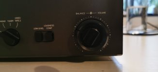
so connected as suggested,1k resistor across terminals and 1k set on generator
pics
1 volume setting
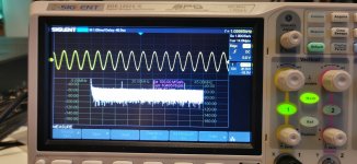
2-amp just before clipping(i presume)
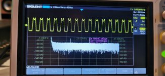
3-clipping? soft clip off
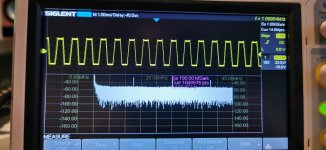
4-with soft clip switch on
but the resistor started to burn
this is my old original NAD 3130 ive had since the 80's(not used since i started learning electronics) and ive never checked it and the off set was 900mv when i tested, so this may be why the resistor is burning?
pics
1 volume setting
2-amp just before clipping(i presume)
3-clipping? soft clip off
4-with soft clip switch on
but the resistor started to burn
this is my old original NAD 3130 ive had since the 80's(not used since i started learning electronics) and ive never checked it and the off set was 900mv when i tested, so this may be why the resistor is burning?
Attachments
Last edited:
The soft clip works well 🙂
You can try this next. Turn the signal level on the generator right down and then set the volume on the NAD to about half way.
Now increase the level of the generator to give say 6 volts peak to peak (so six squares of amplitude from top to bottom of the sine).
If you now increase the frequency of the generator up past 20kHz and beyond (you will need to change the range switch on the generator) you will reach a frequency where the output falls away. Stop when the 6 squares of amplitude have become 4.2 squares.
That frequency is the point where the voltage output of the amp has fallen to -3db.
Also try this.
Go back to six squares (6 volts peak to peak) at 1kHz but now switch the generator to squarewaves. How do they look on the NAD?
Never test at high power with squarewaves as they are tough on an amp and the load.
Try the squarewave at 10kHz and 20kHz. Have a look at posts #157 to #161 here:
My MOSFET amplifier designed for music.
- Home
- Design & Build
- Equipment & Tools
- Siglent SDS1202X-E New to use of equipment.