MarcelvdG, that circuit has some nice tricks! I like the bootstrapped pair configuration with EF86 and ECC83 cathode follower. Why an ECC83 as the cathode follower, though? Anode current of 1mA is enough to drive the feedback loop without loading down? V2A is driving V3 with a 23.7k ohm series resistor, which defines the input impedance of V3 once the NFB loop is closed. Isn't that a heavy load for an ECC83 cathode follower? Or is there something else compensating for that?
It's ten years ago, but I think I looked in a shoebox full of second-hand tubes that I had bought and picked the ones that had a high enough cathode-to-heater voltage rating and the highest gm*(ri Zload/(ri + Zload)). I think the ECC81's in the same box had a too low heater-to-cathode voltage rating and E88CC's a too low mu (=gm ri).
A triode with high mu, high gm and high cathode to heater voltage rating would have been better.
MarcelvdG: Yes, but only by squashing down its gain. Could be achieved better by degeneration. That old Fisher design is just too primitive now. For example, the 75uS pole could be better implemented as part of the anode follower second stage, like the one you posted. Better in every way.
Although I would worry about an an anode follower for the first stage. Noise issues, etc.
All good fortune,
Chris
Although I would worry about an an anode follower for the first stage. Noise issues, etc.
All good fortune,
Chris
I haven't got time to write out the noise transformations at the moment, but I think the effect of the second stage's shunt feedback on the equivalent input noise will be quite small. To be continued.
If the second tube had an infinite transconductance, the shunt feedback network would have exactly the same effect on the equivalent input noise as when it had been connected from the anode of the first tube to ground. The same approximately holds with a finite transconductance when it is much greater than 1/feedback impedance.
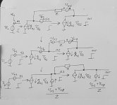
In the attachment, both tubes are modeled as voltage controlled current sources with a noise voltage source at their input. Shifting the second tube's noise through the feedback node results in two equal noise voltage sources, one in series with the first controlled source (which has no effect) and one in series with the feedback impedance Z. That one can be converted into a noise current source, together with the feedback impedance's noise (Thevenin-Norton transformation). This current source can be split into two sources to ground.
With just an impedance to ground, you get the same result except for the noise current source shunted across the output.
Attachments
Last edited:
Yes, and in most any practical circuit the second stage's noise contribution can be ignored.
My concern would be in a conventional C. P. Boegli style anode follower for the first stage, where a series 47K resistor would provide cartridge loading, and looking again, this doesn't appear in the schematic you posted. However, without this, parallel feedback to the first stage grid has the cartridge's frequency-variant impedance as the other leg of the feedback voltage divider, instead of the series sum of cartridge impedance plus 47K Ohm (Boegli).
Both options scare me because of cartridge impedance frequency response dependencies, with the Boegli option having an extra noise penalty.
Given the tiny distortions at phono cartridge levels, a good case can be made for just running the first stage wide open, in the modern fashion. The OP's concern with controlling input capacitance, and in input loading in general, is important and tricky to the level that I'm afraid to introduce feedback here. Edit: "here " meaning at the grid, not at the cathode.
All good fortune,
Chris
Last edited:
However, 6GK5 is also interesting. Higher mu (70 on the data sheet), very low inter-electrode capacitances (Cga = 0.52pF). Its input capacitance can be kept down well below 100pF. If it's 75pF (should be achievable) and your input cabling is 100pF (also achievable) you can get the load capacitance down to <200pF, which is within the optimal range for contemporary MM cartridges like Audio Technica, Nagaoka, Ortofon, etc.
I agree. 6GK5, PC86 and PC900 are quite modern tube designs aimed at low noise and low Cin. I used all of them in combinatin with contemporary MM cartridges and they work well.
Best regards
Philipp
Well, this has been an interesting discussion. Thanks to everyone for their contributions.
The original question was whether the super-low Cg1a spec of the EF184/6EJ7/6J51P meant that it would have very low Cin when wired triode. It looks like the answer is no. The Cin including Miller effect is probably in the same ballpark as that of a 12AX7. (Ignoring 1/f noise considerations, etc.)
The discussion of how NFB in a phono stage affects Cin has been very instructive. By all means, keep it up if you're so inclined. Good stuff indeed!
Since I'm comfortable with the passive EQ topology, I'm left with re-inventing the wheel (again!) with a choice between a hybrid FET-triode cascode or choosing a high mu/low Cga triode like 6GK5, PC900, etc. That's fine.
As suggested in a previous post, I'm currently trying a 12AT7/ECC81 as input triode and it's worked well with a Shure M35X, now that I'm using a tonearm-to-preamp cable with only 80pF capacitance (hard to find).
That Shure M35X -- having recommended load C of 250pF -- sounded very wrong with a 12AX7 as input triode, I assume that was because of the 12AX7 Cin of ca. 200pF added to the 110pF cable capacitance of my previous tonearm-to-preamp cable and the 30pF from the internal tonearm wiring (extimated Cload = 340pF).
I'm going to give the 12AT7 preamp a listen with the ATVM95E. I figure the Cin of a 12AT7 with 120k Rp and red LED bias (Ip = 1.5mA) is around 100pF. Adding 80pF for the cable and another 30pF for the tonearm wiring and I'm down in the ca. 200pF ballpark for total load capacitance, which is within the mfg's recommendation for that current-production MM cartridge.
Some personal consideration.
The use of active or passive riaa is not a problem if the circuit is well dimensioned; both can give a good performances
I prefer the passive riaa and, as possible with a low Rp of tubes and a low Z of riaa network.
With a good HT stabilization this is the only way to get a very good s/n .
The precision is another aspect but it can be trimmed only with a proper test setup.
The circut I use was put in this section as " Junior phono" and the other presented here with photo comes from that topology basically with some better solution and the 184 as gain stage ( I will test the E280F, great tube) .
The s/n of 82-84 dB (with gain of 42 dB) I got ( variable with tube selections, another aspect!) is very high and difficult (impossible) to reach with the normal tubes as 81,83,88 or similar.
Another aspect to be considered is the max level in input.
to rongon
If you feel well with 81 left it , the 50-80 pF of difference is not dramatic.
I think that the 83 is not a very good tube for this purpose; I prefer the 81, the 7062, the 12AZ7.
Walter
Last edited:
I am working with PC900, it is interesting . I have 120 pcs!!!
But not so easy to configure for best performances
Walter
But not so easy to configure for best performances
Walter
I've recently purchased a few EC97 and 6GK5.
What is the difficulty in configuring PC900 for best performance?
PC900 looks similar to 4GK5, PC97, etc except for slightly lower Cga --
(typical characteristics)
PC900
mu = 76
gm = 14mA/V
Cga = 0.365pF
PC97
mu = 65
gm = 13mA/V
Cga = 0.5pF
6GK5
mu = 78
gm = 15mA/V
Cga = 0.52pF
What is the difficulty in configuring PC900 for best performance?
PC900 looks similar to 4GK5, PC97, etc except for slightly lower Cga --
(typical characteristics)
PC900
mu = 76
gm = 14mA/V
Cga = 0.365pF
PC97
mu = 65
gm = 13mA/V
Cga = 0.5pF
6GK5
mu = 78
gm = 15mA/V
Cga = 0.52pF
Last edited:
PC900 has 84 of mu and 20mA/V as gm
From Philips data sheet.
In the configuration I am testing I set at the upper limit the set point.
Walter
From Philips data sheet.
In the configuration I am testing I set at the upper limit the set point.
Walter
That's why I specified "typical characteristics". The Philips data sheet puts those specs on the first page as their Quick Reference Data (likely not realistic usage), but then shows a second set of characteristics that are for Vp = 135V, Vg = -1.0V, Ip = 11.5mA, which is more realistic.
I think the characteristics will again be different of Vp = 130V and Ip = 5mA, where gm would be more like 3.5mA/V, and mu lower too.
I think the characteristics will again be different of Vp = 130V and Ip = 5mA, where gm would be more like 3.5mA/V, and mu lower too.
Yes, and in most any practical circuit the second stage's noise contribution can be ignored.
My concern would be in a conventional C. P. Boegli style anode follower for the first stage, where a series 47K resistor would provide cartridge loading, and looking again, this doesn't appear in the schematic you posted. However, without this, parallel feedback to the first stage grid has the cartridge's frequency-variant impedance as the other leg of the feedback voltage divider, instead of the series sum of cartridge impedance plus 47K Ohm (Boegli).
Both options scare me because of cartridge impedance frequency response dependencies, with the Boegli option having an extra noise penalty.
Given the tiny distortions at phono cartridge levels, a good case can be made for just running the first stage wide open, in the modern fashion. The OP's concern with controlling input capacitance, and in input loading in general, is important and tricky to the level that I'm afraid to introduce feedback here. Edit: "here " meaning at the grid, not at the cathode.
All good fortune,
Chris
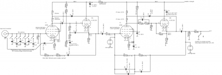
I agree that putting a big resistor in series with the signal source is not the way to achieve low noise, but neither my circuit (first attachment) nor the Fisher circuit that PRR posted (second attachment) does that. In both cases, the cartridge is connected straight to a common-cathode stage (triode-connected EF86 in my case, 6SC7 or something like that in the Fisher circuit). Like I wrote, with AC heater supply, an advantage of AC grounding the cathode is the reduced sensitivity to hum currents that get from the heater into the cathode, for example via heater emission, capacitive coupling or leakage resistance.
In my case, the first common-cathode stage and first cathode follower together form an inverting amplifier with a gain of about -30. The shunt feedback is only used to realize a 47 kohm input resistance with less than thermal noise. The frequency-dependent voltage division between the cartridge and the input impedance is no different than if I had used a 47 kohm resistor to ground instead of the trick with the shunt feedback. Because of the large voltage gain, there is a lot of Miller effect, giving an input capacitance of about 90 pF. The second part is an inverting RIAA-equalized negative-feedback amplifier. The 23.7 kohm resistor generates some noise, but because it is after an amplifier that amplifies by -30, it hardly has any impact on the overall noise.
In the Fisher circuit, the common-cathode stage directly drives the virtual ground input of an equalized transimpedance amplifier (current to voltage converter, anode follower, whatever you want to call it). That reduces the signal swing at the first anode and hence the Miller effect without much of a noise penalty, see post #84. I think it is conceptually a really nice circuit, even though there may be details that are not so nice.
I don't like the way Fisher biased the first triode much. The bias current is not very predictable and the AC coupling capacitor makes the circuit extra sensitive to hum currents that couple into the grid.
I don't know why they realized one of the poles with an extra low-pass at the output rather than in the feedback of the second stage; maybe related to the switching of time constants depending on the desired correction curve? When you only want to have RIAA correction, I don't see any reason not to put it all in the second stage's feedback network.
It's not clear to me what PRR and you mean by "wide open".
Attachments
Last edited:
Much thanks for your always insightful comments, and I'm sorry for using a term maybe particular to guys of a certain age and location. "Wide open" is used as in "wide open throttle", e.i. without feedback's restriction of flow, by geezers around here.
Your description of the artificially generated 47K load resistor is very complete, but I'll need to process it some before I can understand how it's independent of the cartridge's complex impedance. I've seen something similar in the Yamaha C-4 preamp, and didn't understand it back then either!
Much thanks, as always,
Chris
It's basically the same as Miller effect, but with a resistor instead of a capacitor. When you have a stage with a voltage gain of -µ and you connect a resistor between its input and output, you get µ + 1 times the input voltage across it, so the current through it is µ + 1 times as large as if it had been a resistor to ground, so you effectively see an µ + 1 times smaller resistance at the input.
The voltage division between the cartridge and the 47 kΩ load is frequency dependent, but the frequency dependence is the same no matter how you make the 47 kΩ load.
The voltage division between the cartridge and the 47 kΩ load is frequency dependent, but the frequency dependence is the same no matter how you make the 47 kΩ load.
Attachments
Last edited:
"The voltage division between the cartridge and the 47 kΩ load is frequency dependent, but the frequency dependence is the same no matter how you make the 47 kΩ load."
Bingo! I finally understand. Thank you very much for your help. It's very kind of you.
Chris
Bingo! I finally understand. Thank you very much for your help. It's very kind of you.
Chris
I agree. 6GK5, PC86 and PC900 are quite modern tube designs aimed at low noise and low Cin. I used all of them in combinatin with contemporary MM cartridges and they work well.
Even less Cga can be seen in the PC88, which is the PC86's succedessor in the 1st stage of European UHF frontends. This is acheived by an asymmetrical plate structure that is exclusively arranged at one side of the rectanguler catode. The PC86's plate structure resembles that in the E88CC/6922 family of double triodes and the PC97.
The PC900's low C[sub[ga[/sub] is due to an pair of shielding plates between grid and plate. It' cross section resmbles that of a beam power tube (less g2, of course). This tube was designed to replace the PCC88 cascode in European VHF TV frontends. According to the TELEFUNKEN Laborbuch Bd. IV (laboratory book vol 4) it nearly provided the same gain as the former cascode.
Best regards!
I have read the posts of Marcel that are interesting but my question is if these type of approach is better than standard configurations.
I mean, there are evidences of test labs who can explain the benefits?
We are speaking around +/- 50 pF of difference (maybe 100) as the basic to have a good performance while the issues are in other parts of each phono circuit
Walter
I mean, there are evidences of test labs who can explain the benefits?
We are speaking around +/- 50 pF of difference (maybe 100) as the basic to have a good performance while the issues are in other parts of each phono circuit
Walter
The input capacitance of my circuit is about as bad as it gets when using a triode-connected EF86, about 90 pF.
The equivalent input noise current is lower than that of any amplifier with a 47 kohm resistor across the input. I measured 14.38 pA RIAA- and A-weighted, which corresponds to a noise current density of 0.2534 pA/√Hz. A 47 kohm resistor at room temperature produces 0.5869 pA/√Hz.
The equivalent input noise voltage was 582.3 nV RIAA- and A-weighted, corresponding to 10.26 nV/√Hz. Not very good, but as good as it gets with a triode-connected EF86. I chose an EF86 because of its small capacitance from heater to grid, to get low hum with a plain old AC heater supply.
As it's a hobby circuit, I measured all that at home and not in a fancy test lab. I mainly used an HM-1505 oscilloscope and an antique BKF6d distortion meter / true RMS (milli-)volt meter.
Whether the low equivalent input noise current is useful depends on whether you care about the noise level between records. As soon as you play a record, record surface noise dominates anyway.
I have no idea what was measured for the Fisher circuit, maybe PRR does.
I have understood your post but effectively you haven't done the proper full test on this circuit.
I mean that the s/n is not the only parameter to consider even if it is always better to have it at the lowest possible level; I know that the surface of the disc is noisy but this is not a reason to have it not at the best.
Then, in a tube phono I try to use, possibly, the best power supply also for filaments.
There are no reason to use ac voltage for them in a phono stage.
Also the toroid trafo have a screen between primary and secondary and a external coil to reduce at maximum the residual flux ( even if it is low, in general)
In addition, if I have an high acceptance in input at 1kHz ( as standard) and 20 dB lower at 20 Hz with a low THD probably the sonic results are good at the normal level.
I add also the andament of THD vs frequency at different level , if it is linear probably I have the circuit that works fine.
Last, the accuracy on frequency answer, it is difficult to get specialy for both channels due the tolerance of components.
One more thing about the balance on tubes between channel with different signal level.
Personally I select the tubes on circuit to have the same Vout for the same Vin but also the same THD vs frequency
Of course the noise level must be the same.
Also microphonics must be considered. The Phono Stage in photo have two big plate of 5 mm thick of teflon suspended each one with silent block, the phono pcb is also suspended with little silent block ; this helps.
Walter
Last edited:
- Home
- Amplifiers
- Tubes / Valves
- EF184 in triode for phono stage input?