Onward ho!
Thanks 6L6
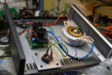
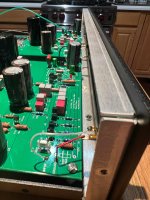
Making progress -- building the PSU
I measure +30.268vDC and -30.268vDC at the XLR -- good, correct? Case from ParMetals
Question: The BrianGT "Chipamp" PSU has a small circuit for the LED -- but I measure 30vDC across the LED Anode/Cathode pads [ergo -- the LED would not last long] -- are there suggestions as to how to mod that to work, or better to just leave off?
-- Charles
Thanks 6L6
Making progress -- building the PSU
I measure +30.268vDC and -30.268vDC at the XLR -- good, correct? Case from ParMetals
Question: The BrianGT "Chipamp" PSU has a small circuit for the LED -- but I measure 30vDC across the LED Anode/Cathode pads [ergo -- the LED would not last long] -- are there suggestions as to how to mod that to work, or better to just leave off?
-- Charles
Attachments
Last edited:
Voltages look about right for 22VAC transformer with no load.
Looking at your picture it looks like there is no LED installed but there is a voltage dropping resistor in place. With an open circuit there are no electrons flowing so the dropping resistor does not drop any voltage, therefore you measured full voltage. You need to install the LED to get a proper voltage reading.
Looking at your picture it looks like there is no LED installed but there is a voltage dropping resistor in place. With an open circuit there are no electrons flowing so the dropping resistor does not drop any voltage, therefore you measured full voltage. You need to install the LED to get a proper voltage reading.
Pass DIY Addict
Joined 2000
Paid Member
Yep, need a load in series with that resistor to see any voltage drop. In general, a ~10k resistor will give you an adequate starting place to run an LED from a 30v power supply.
Specifically use Ohm's Law to calculate the optimal resistor value: (30v PSU - forward voltage drop of LED) / current draw of LED.
This will likely be faaaar too bright, so double or even triple the calculated resistor value. Adjust to taste. Just leave the surface mount resistor in place and adjust with a second resistor in series if necessary.
Esteemed moderator 6L6 offers the pragmatic rule of thumb "start your experimentation using 1 kilohm of resistance per volt of supply." He reasons that modern LEDs are indeed very VERY good at converting electricity into bright light, and so ~ 1 milliamp is a good starting point. If that makes the LED too bright for your tastes, increase the resistance and try again. If you find the LED too dim, decrease the resistance and try again. Remember that the goal is to maximize your own enjoyment, which varies from person to person, so what's good for Alice might not be so great for Bob. And vice versa.
_
_
Last edited:

E Remember that the goal is to maximize your own enjoyment, which varies from person to person, so what's good for Alice might not be so great for Bob. And vice versa.
How about Ted and Carol?
Saw BCTA when it was first released...1969
Quick question about the 0.0033uF capacitor from the original PS schematic: what type is it? Ceramic? I assume the voltage rating is the same as AC outlet - 240V or higher?
Where did you guys mount this capacitor in your PS, directly on the AC socket pins?
Is this from the link below ok?
Blocked
Where did you guys mount this capacitor in your PS, directly on the AC socket pins?
Is this from the link below ok?
Blocked
Trouble-Shooting Suggestions?
Ok -- so every hooked up and one card tested perfectly --, and I am able to achieve a zero [+/-0.005v] voltage at at the [P1] offset checkpoint.
My other card is giving me troubles:
When I first powered it up, no LED, and something started smoking (this turned out to be R 29 -- 100)
The LED had its polarity flipped [the silkscreen is miss-marked with a "square" where the anode goes, though the diode flat is in the right place ]-- so I changed that, but when powered up, still R29 started to burn up/smoke .
So I swapped both ZTX450 [Q10-Q11] and Q2 [ZVP3310] paying extra attention to ESD handling, and replaced the 100ohm R29 and redid the R14 1K + 220uF fix.
Powered up, and LED is lit, but now I get a "solid" 23Vdc reading at the P1 zero 0vDC test point -- no amount of adjusting seem to move the voltage -- nothing seems to be getting hot, and the PSU fuse does not blow, but wondering what to do now -- leave it and try to see where voltages are going askew [which might burn/ruin something(?) ] -- does anyone have any suggestions?
Ok -- so every hooked up and one card tested perfectly --, and I am able to achieve a zero [+/-0.005v] voltage at at the [P1] offset checkpoint.
My other card is giving me troubles:
When I first powered it up, no LED, and something started smoking (this turned out to be R 29 -- 100).........
Hi
For R29 to burn out, you need to have a high voltage difference across it. My guess (and it is only a guess) is that Q11 failed/shorted and it shorted out Q2 as well. That gave you a + and - 23V across R29 turning it into a mini heater. Replacing Q11 fixed that problem.
There are a couple of options I can see for 23V at the test point. Either Q2 has shorted again (very unlikely, but possible) or the presence of the higher than normal voltage due to the previous problem caused the gate and drain on Q5 to short, allowing the +ve voltage to flow through to the test point. Try unsoldering one end of R16. If the test point voltage drops, while the R15 jumper is still at 23V, then Q5 is the culprit and Q4 & Q5 should be changed. If the test point is still at 23V, then it's Q2.
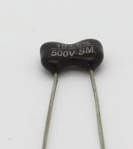
Just out of curiosity, have you installed C7 or left it out? The mica capacitor is rated at 500V and they rarely fail, but you never know!
C7 is populated (on both good and bad card)
I have C7 populated -- using a silvered mica 10pF (rated at 500V) -- 6L6 just suggested that I leave in, though I see many are taking this out -- Wayne describes these thus: "C7 and C9 provide frequency compensation"
Just out of curiosity, have you installed C7 or left it out? The mica capacitor is rated at 500V and they rarely fail, but you never know!
I have C7 populated -- using a silvered mica 10pF (rated at 500V) -- 6L6 just suggested that I leave in, though I see many are taking this out -- Wayne describes these thus: "C7 and C9 provide frequency compensation"
Attachments
Fastest Path?
So -- relative to the board that is not testing well POST-2870 -- perhaps the "fastest path" would be to replace all the active components [including the regulators]? My worry is that if I power it on to find where 'something is awry', that will cause issues with other components, which will eventually (but not immediately) fail, because of being exposed to inappropriate voltages. Given that I "solder well" [40+ years experience] , it is unlikely to be a cold solder joint, as in low probability.
So -- relative to the board that is not testing well POST-2870 -- perhaps the "fastest path" would be to replace all the active components [including the regulators]? My worry is that if I power it on to find where 'something is awry', that will cause issues with other components, which will eventually (but not immediately) fail, because of being exposed to inappropriate voltages. Given that I "solder well" [40+ years experience] , it is unlikely to be a cold solder joint, as in low probability.
I have C7 populated -- using a silvered mica 10pF (rated at 500V) -- 6L6 just suggested that I leave in, though I see many are taking this out -- Wayne describes these thus: "C7 and C9 provide frequency compensation"
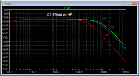
Here's the effect of C7 assuming 1fF, 5pF and 50pF. If you had a voltage network analyzer (VNA) you could interrupt the feedback loop and see how different values affect stability. Leave C7 in.
Attachments
Here's the effect of C7 assuming 1fF, 5pF and 50pF. If you had a voltage network analyzer (VNA) you could interrupt the feedback loop and see how different values affect stability. Leave C7 in.
I had severe offset swings with C7 in place. When I took C7 out they settled right down and the sound improved. I am curious as to why C7 can have negative effects in some builds.
Referring to C9 (instead of C7)?
I think you mean C9 (which I mistakenly called C5 in my list) -- that (C9) is a 5pF -- C7 is a 10pF cap -- but likely to have some of the same effects on the graph that you show (which also shows C9).
I kinda want to build the circuit to Wayne's spec -- so, aside from the "R14 + cap" adjustment, I wanted to keep C7 (and C9)
I want to try @vcec suggestion of lifting a leg R16 to isolate -- given that my next step is to atomic bomb all the actives and replace, I don't see what I have to lose.
But thanks -- I read/digested your observations on equalization earlier in this chain -- thinking about how to optimize for a 0.4mv MC (new ATOC9XLS).
So -- relative to the board that is not testing well POST-2870 -- perhaps the "fastest path" would be to replace all the active components [including the regulators]? My worry is that if I power it on to find where 'something is awry', that will cause issues with other components, which will eventually (but not immediately) fail, because of being exposed to inappropriate voltages. Given that I "solder well" [40+ years experience] , it is unlikely to be a cold solder joint, as in low probability.
I you want to eliminate every possibility, then replacing the active components on the output side of the board (Q2, Q4, Q5, Q10 & Q11) would do it. The input side of the board is DC isolated from the output side by C12 & C16, so the active components on the input side (Q1, Q3, Q6, Q7, Q8 & Q9) should not cause the results your seeing on the output side of the board. The DC isolation also means that a fault on the output side won't damage components on the input side.
Once you've removed the active components, you can apply power to the board and check the regulator voltages, just to make sure everything is OK.
As for C7, many people (myself included) have left it out with no ill effects. If you want to leave it in, then when you check the regulators, you can also make sure that there's approximately +24V on one side of C7 and 0V on the other.
Let us know how it works out.
All good -- inverted Q2
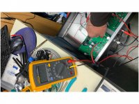
Just as I was getting ready to play destructo-boy and clip all my active components, I took a careful look at things carefully (again) -- and (darnit!) notice that my Q2 MOSFET was oriented the wrong way -- AND I gave you guys bum dope, FYI, as the voltage at the test point was -23.6vDC (as we were only getting negative voltages) -- pulled Q2 out and placed another in (correctly), and bingo!
The preamp is very percussive, I don't remember my headphones ever going this deep -- now onto finial testing, then to hook it up to the "big" system. I did need to clip C7 leg out, as there was a very audible oscillation occurring. Thanks for the insight and help!
Attachments
Last edited:
- Home
- Amplifiers
- Pass Labs
- Building a Pearl 2