I suggest building it in it’s own enclosure with a separate PSU. Grounding (and noise) can get very tricky.
Last edited:
Hello guys,
I have decided to build a Pearl 2 myself as fun and remembering my teenage time when I was passionate about electronics as a hobby. Meantime I became a mechanical engineer so I am by no means a specialist. I can solder, I know the basic concepts - capacitors, transistors, etc and how they work by cannot decide on components values..schematics ...etc.
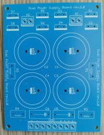
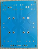
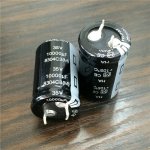
Before ordering the 2 PCB's would like to have a start on the power supply. I have ordered from Ebay a generic board which in my mind was the closest I could find compared to the original design - see attaches both sides of the PCB.
First of all - please le me know if I drew correctly the schematic of the purchased PCB.
Second - can you please let me know if I should leave out (not use) R3, R4, C5, C6 and connect with wire R2 and R1?
Third - since I have space for 4 capacitors 30mm diam each, should I stick to the original design - 2 x 10000 uF / 4 x 5000 uF or should I go with more and if yes how much?
I hope that I will get from you guys the help to build this successfully
I have decided to build a Pearl 2 myself as fun and remembering my teenage time when I was passionate about electronics as a hobby. Meantime I became a mechanical engineer so I am by no means a specialist. I can solder, I know the basic concepts - capacitors, transistors, etc and how they work by cannot decide on components values..schematics ...etc.
Before ordering the 2 PCB's would like to have a start on the power supply. I have ordered from Ebay a generic board which in my mind was the closest I could find compared to the original design - see attaches both sides of the PCB.
First of all - please le me know if I drew correctly the schematic of the purchased PCB.
Second - can you please let me know if I should leave out (not use) R3, R4, C5, C6 and connect with wire R2 and R1?
Third - since I have space for 4 capacitors 30mm diam each, should I stick to the original design - 2 x 10000 uF / 4 x 5000 uF or should I go with more and if yes how much?
I hope that I will get from you guys the help to build this successfully
Attachments
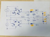
1) wrong diode drawing on lower bridge
2) I'd use use 3W 10 Ohm (or lower) as R1 and R2 for a CRC filtering
2) I'd use use 3W 10 Ohm (or lower) as R1 and R2 for a CRC filtering
Hello guys,
I have decided to build a Pearl 2 myself as fun and remembering my teenage time ........
Don't forget some bleeder resistors to drain the capacitors in case the power supply is turned on without being connected to the amplifier.
I agree with the previous 2 comments, so you could replace C5 and C6 with jumpers and use R3 and R4 as bleeder resistors. About 1K to 2K and 2W should do.
Cheers
Vic
...or use left R4 hole and right C6 hole & left C5 hole and right R3 hole for bleeder resistors, without jumpers
...or use left R4 hole and right C6 hole & left C5 hole and right R3 hole for bleeder resistors, without jumpers
Yes! Even simpler 🙂
Cheers
Vic
Summary of suggested changes to Pearl Build:
Hello 6L6:
Thanks for this, but I have seen the following -- any I missed (C6??):
I appreciate all of your help and support in this forum.
Hello 6L6:
Leave R3 R4 C5 C6 open.
Thanks for this, but I have seen the following -- any I missed (C6??):
- Add a zobel network consisting of a 680r resistor and 1000pf cap in series across the inputs [Accross PAD5/PAD6] [Why: Solve High input impedance cartridge issues]
- Lift R14 and place 220uF/35v (w/0.1uF Poly) +lead to R14 -lead Ground [Why: Stabilize output voltages]
- Remove/leave off 10pF C7 [Why: Prevent high-freq motor-boating ]
- Remove/leave off 5pF C5 [Why: Prevent high-freq motor-boating ]
I appreciate all of your help and support in this forum.
RE: Summary of suggested changes to Pearl Build
OK (sorry) -- got it -- if possible, can you verify/comment on this list though -- in the throws of building my Pearl, and I want to make it right
I’m referring to shomescu’s PSU, not the Pearl boards.
OK (sorry) -- got it -- if possible, can you verify/comment on this list though -- in the throws of building my Pearl, and I want to make it right
- Add a zobel network consisting of a 680r resistor and 1000pf cap in series across the inputs [Accross PAD5/PAD6] [Why: Solve High input impedance cartridge issues]
- Lift R14 and place 220uF/35v (w/0.1uF Poly) +lead to R14 -lead Ground [Why: Stabilize output voltages]
- Remove/leave off 10pF C7 [Why: Prevent high-freq motor-boating ]
- Remove/leave off 5pF C5 [Why: Prevent high-freq motor-boating ]
Leave R3 R4 C5 C6 open.
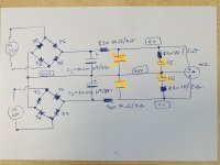
Thanks taking your time guys to reply for my help. Here is a summary of what has been proposed:
1) wrong diode drawing on lower bridge (peppennino)
2) use 3W 10 Ohm (or lower) as R1 and R2 for a CRC filtering (peppennino)
3) Leave R3 R4 C5 C6 open (6L6)
4) bleeder resistors to drain the capacitors in case the power supply is turned on without being connected to the amplifier - replace C5 and C6 with jumpers and use R3 and R4 as bleeder resistors. About 1K to 2K and 2W should do (vcec)
I have corrected the lower bridge - 1) and added R1 & R2 per - 2) - and R3 and R4 per 4).
I know that 6L6 gave me the advice to leave out R3 R4 C5 C6 so at this point I am split between directions 🙂
As far as capacitors after a lot of search I have found on Mouser Nichicon UKT and on Ebay Panasonic HA. Thought it was easier to find this 10k capacitors...
Which one do you think is better to use?
Attachments
I would leave the second set of caps in so you have a nice CRC filter.
Have you considered using the C5/C6 spots for LEDs so you can see the PS is powered
up?
About caps: Why not pick something currently available on mouser and not
resort to ebay? Here's a nice one, and there are many others:
https://www.mouser.ca/ProductDetail.../381LX153M035K452?qs=nnhpPVbCybVFiyi7cda1NA==
Good luck with your build.
Dennis
Thanks Dennis Hiu.
Did you mean to leave also C3 and C4 and have in total 4 x 10.000 uF?
Nice idea with the LED's I like it and will do so but...I have no clue how to spec the LED's 😀
As practice these LED's stay on the PCB for quick visual troubleshooting when open the chassis or folks also install them to be visible on the chassis of the PS?
Yes, I was suggesting you keep C3 and C4. Though now that I look at the
Pearl 2 schematics, there's an RC filter at the power input. Certainly having
C3 and C4 won't hurt and should make the supply even quieter.
One thing about the caps is that you probably should consider those with
diameter <=25 mm because that's the spacing available on the Pearl 2 PCB
for the power supply caps. So you might as well use the same ones in both
positions.
Spec'ing the led shouldn't be hard. Drop me a PM if you're interested.
1) wrong diode drawing on lower bridge
2) I'd use use 3W 10 Ohm (or lower) as R1 and R2 for a CRC filtering
These CRC filtering resistors need to be wire wound type?
These CRC filtering resistors need to be wire wound type?
No, resistors R1 and R2 in the CRC filter do not need to be wire wound. Whatever is easier to get will be fine.
Cheers
Vic
These CRC filtering resistors need to be wire wound type?
I think Mr. Pass has an affinity for the Panasonic 3 Watters.
Add a zobel network consisting of a 680r resistor and 1000pf cap in series across the inputs [Accross PAD5/PAD6] [Why: Solve High input impedance cartridge issues]
Not necessary unless you have a very high output HOMC, the 2 times this happened it was with the same model cartridge... the SAE 1000E
Lift R14 and place 220uF/35v (w/0.1uF Poly) +lead to R14 -lead Ground [Why: Stabilize output voltages]
Yes.
Remove/leave off 10pF C7 [Why: Prevent high-freq motor-boating ]
Leave that one in.
Remove/leave off 5pF C5 [Why: Prevent high-freq motor-boating ]
C5? That's 3300uF and part of the cap multiplier in the front-end's PSU. I think you mean C15, and yes, leave empty.
- Home
- Amplifiers
- Pass Labs
- Building a Pearl 2