Congrats!
Yep! it's always the little thing you miss that leads you up the garden path and are the hardest to find. The number of times I've torn my hair out wondering what the hell was going on only to find I'd missed soldering a pin or put in 22 ohm instead of 22K (that was exciting!). Good that you found it before you tore the board apart. And yes, it's a very nice, detailed and fast sounding preamp. Good listening!
Just as I was getting ready to play destructo-boy and clip all my active components, I took a careful look at things carefully (again) -- and (darnit!) notice that my Q2 MOSFET was oriented the wrong way -- AND I gave you guys bum dope, FYI, as the voltage at the test point was -23.6vDC (as we were only getting negative voltages) -- pulled Q2 out and placed another in (correctly), and bingo!
The preamp is very percussive, I don't remember my headphones ever going this deep -- now onto finial testing, then to hook it up to the "big" system. I did need to clip C7 leg out, as there was a very audible oscillation occurring. Thanks for the insight and help!
Yep! it's always the little thing you miss that leads you up the garden path and are the hardest to find. The number of times I've torn my hair out wondering what the hell was going on only to find I'd missed soldering a pin or put in 22 ohm instead of 22K (that was exciting!). Good that you found it before you tore the board apart. And yes, it's a very nice, detailed and fast sounding preamp. Good listening!
Pass DIY Addict
Joined 2000
Paid Member
Congrats on solving your problem! My usual go-to list of "things to check" is:
1) verify ALL parts value with a meter BEFORE installing - I've been sent 100R resistors in a bag marked 100k on more than one occasion
2) if mounting large power mosfets - be sure the mounting surface has been de-burred. After mounting but BEFORE soldering, use DMM to make sure middle pin to sink connectivity reads open loop. Silpads are notoriously easy to puncture with tiny aluminum slivers causing an invisible short. This is why I now prefer aluminum oxide ceramic insulators and goop.
3) check for cold solder joints - use a bright light and a magnifier, reflow everything. Be sure plated through-hole pads are completely filled
4) near-invisible solder bridges across adjacent pads - use a fine tip screwdriver to scratch between ALL pads, use same bright light and magnifier to inspect when finished
5) parts placement/orientation - I've mixed up N-Ch and P-Ch devices before (causing me to have to remove MORE parts later on) and orientation of 3-legged critters
6) as a last resort, replace small 3-legged critters most adjacent to any burned components
Usually, this gets me up and running.
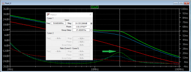
I was going through Bob Cordell's "Designing Audio Power Amplifiers" to find an example of C7. The thought came to me that the output MOS has significant parasitic inductance, so let's see what happens if C7 is simulated as 1fF, 5pF and 50pF.
Instead of plotting phase on the right Y-Axis, I plot group delay. The "Q" of this circuit at 19.6MHz is:
Q= Tg * f * pi = 21.6ns * 19.6MHz * pi = 1.3
When C7 is 1fF the output PMOS is not adequately damped. With C7 of 5pF, group delay is cut in half and the circuit is adequately damped.
This is a guess. Will put it on the network analyzer to see what's going on in reality.
Attachments
Me mates created a Wikipedia article to educate the world about Alice and Bob: (Link)
I do not know about anyone else, but I found that link pretty dang funny; especially "Grace".
What about when C7 == 10pf ?
Thanks -- what does the spice model show when C7 = 10pF (the value that Wayne had us put in) ?
I was going through Bob Cordell's "Designing Audio Power Amplifiers" to find an example of C7. The thought came to me that the output MOS has significant parasitic inductance, so let's see what happens if C7 is simulated as 1fF, 5pF and 50pF.
Instead of plotting phase on the right Y-Axis, I plot group delay. The "Q" of this circuit at 19.6MHz is:
Q= Tg * f * pi = 21.6ns * 19.6MHz * pi = 1.3
When C7 is 1fF the output PMOS is not adequately damped. With C7 of 5pF, group delay is cut in half and the circuit is adequately damped.
This is a guess. Will put it on the network analyzer to see what's going on in reality.
Thanks -- what does the spice model show when C7 = 10pF (the value that Wayne had us put in) ?
Got it hooked up to the big system -- and it sounds great!
Finally! After making some unintended mistakes, my Pearl II is playing “like it was supposed to”, or more to the point, as it was designed to sound/play.
Mistake One:
Inverting the output at the output RCA. This was a bad idea -- the sound was compressed and strange -- leave the output polarity to the RCA “as is” and forget about absolute phase
Mistake Two:
Leaving the C8 0.1 uF output coupling cap (with C13) -- removing C8 and shorting this opened up the sound-stage, giving me the realism that I had been hoping for.
Notes: Sound-stage is wide and deep, bass is deep with impact, but a little bit emphasized. Voices are natural. Does “relay” ticks and scratches with emphasis, but very quiet. Compares well with my current reference [The RJM Emerald]. Does not handle MM particularly well; A Shure V15 sounded like it was overloading the input stage -- some distortion, and very loud. A ZYX Omega gave a much better result.
Does not handle MM particularly well; A Shure V15 sounded like it was overloading the input stage -- some distortion, and very loud. A ZYX Omega gave a much better result.
Well, the Pearl is EXPLICITLY designed for MC carts, of course it is over-loading. Increase the value of the gain-setting resistor 10x.
Finally! After making some unintended mistakes, my Pearl II is playing “like it was supposed to”, or more to the point, as it was designed to sound/play.
Mistake One:
Inverting the output at the output RCA. This was a bad idea -- the sound was compressed and strange -- leave the output polarity to the RCA “as is” and forget about absolute phase
Mistake Two:
Leaving the C8 0.1 uF output coupling cap (with C13) -- removing C8 and shorting this opened up the sound-stage, giving me the realism that I had been hoping for.
Notes: Sound-stage is wide and deep, bass is deep with impact, but a little bit emphasized. Voices are natural. Does “relay” ticks and scratches with emphasis, but very quiet. Compares well with my current reference [The RJM Emerald]. Does not handle MM particularly well; A Shure V15 sounded like it was overloading the input stage -- some distortion, and very loud. A ZYX Omega gave a much better result.
Hi
By shorting out C8, you effectively bypassed the output electrolytic capacitor (C13). I've never been fond of electrolytics in the signal path, which is why it sounds "better" when you bypassed it. However, it now means the circuit is directly coupled to the output, which means if something fails and you suddenly get + or - 23 V at the output, this DC voltage will be sent directly to your preamp. Unless the preamp has an input blocking capacitor, then it may not do your preamp much good! One way around it is replacing C13 with a film capacitor. I asked Wayne why C13 was so big (22uF) and he responded that they used what they had on hand. A 1uF capacitor is more than ample given preamps typically have input impedances of 20K-50K. I used a 1uF Mundorf supreme bypassed with a 0.01uF Duelund Silver Foil Bypass capacitor and it sounds very nice, slightly warm, detailed, extended and smooth. I can't guarantee it sounds as good as no capacitor at all, but it's definitely safer. Use whatever film capacitor floats you boat, or as this is DIY, experiment with different caps.
As for the MM overloading the unit, as Jackinnj stated, the unit in stock form is tailored for MC cartridges, therefore has a high gain. If you want to use MM cartridges, you'll have to adjust the gain by changing the value of R14 and/or R16. I put together a spreadsheet I posted a while ago you can use if you're interested (reply 2758)
Link: Building a Pearl 2
If you want to use MC and MM, you could set up a switch to use different R14 values and vary the gain that way.
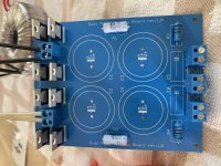
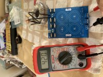
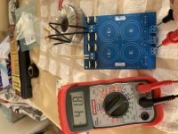
I made some progress guys with the power supply but I have a issue - still missing the capacitors. I have received some parts from Digikey and only today when started to solder I noticed when unwrapping the capacitors that they sent me the wrong stuff. Instead of Cornell Dubilier 50V / 10.000 uF @ 105C they sent me Rubycon 35V / 15000 uF @ 85C. I will write them, hopefully will work out because they sent me the parts from US to Europe.
So I soldered all except the capacitors and LED's.
Tried to see if the thing works so far and I am getting + / - 42 V.
Am I on the right path?
Thanks.
So I soldered all except the capacitors and LED's.
Tried to see if the thing works so far and I am getting + / - 42 V.
Am I on the right path?
Thanks.
Attachments
Hello Guys,
I have received today the correct capacitors from Digikey so I should further progress on the power supply.
Also ordered the 2 PCB's from Passdiy - they are already on the way to Europe.
Going through the BOM to prepare the parts ordering I noticed that:
U1 - IC, Volt Reg 7824, 24V, TO-220 - Mouser # - 512-LM7824CT
is obsolete. Mouser did not suggest any replacement but searching on Digikey obtained the same obsolete result and these 2 replacement suggestions:
PART NO. MANUFACTURER
MC7824CTG onsemi
MC7824ACTG onsemi
Can you please help me pick the correct subsititute?
Also in the BOM I see U1 and U2 each with 2 pcs and same P/N. Should I assume that there are all 4 the same but only listed separately by mistake?
Thanks.
No, U1 and U2 are different polarity regulators. Please see the last page here:
https://www.passdiy.com/pdf/PEARL 2.pdf
You need two positive (7824 for U1) and two negative (7924 for U2)
MC7824ACTG seems to have slightly tighter output voltage tolerance (ie closer to nominal 24V) than the 7824C.
(https://www.mouser.ca/datasheet/2/308/1/MC7800_D-2315963.pdf)
https://www.passdiy.com/pdf/PEARL 2.pdf
You need two positive (7824 for U1) and two negative (7924 for U2)
MC7824ACTG seems to have slightly tighter output voltage tolerance (ie closer to nominal 24V) than the 7824C.
(https://www.mouser.ca/datasheet/2/308/1/MC7800_D-2315963.pdf)
Hello Guys,
I have done hours of reading regarding gain - R14 and load - R20 but could not find something clear regarding values.
I am planning to build first the original project but to avoid extra shipping cost would like to order in advance what is needed for the later mods.
Q1: - R14 values - 3 values: 1k (standard), 300k (custom 1); 600k (custom 2) - is this enough?
Q2: - R20 values - in the xls BOM I downloaded from this forum there is no value listed but in the original Pearl pdf I see 47k Ohm.
Please help me with some values as above for R14. I assume standard project starts with 47k as in Pearl documentation?
Q3: I found in the forum: C15 - leave out; R15 - jumper; C22 - leave out; C7 - leave out. Can you please confirm?
Q4: Can you please recommend a rotary switch to implement for R14 and R20?
Thanks!
Hopefully a quick question. Rather than wait for ztx450 transistors to come back into stock at Mouser and Digikey, I plan to substitute BC550C transistors for my Pearl 2 build. I have found a number of references in other posts saying it is an appropriate substitute, taking into account the different pinout. However, none of those posts related specifically to the Pearl 2. The ZTX450 and BC550C do have some different specs. Assuming it is an appropriate substitute, should I expect to have to make any other adjustments to compensate for using the BC550C? Is there a better substitute for a Pearl 2 build? It looks like a number of the BC transistors could be substituted for the ZTX450, at least for other projects. I am not sure if the Pearl 2 is more particular.
@flip69 -- will workHopefully a quick question. Rather than wait for ztx450 transistors to come back into stock at Mouser and Digikey, I plan to substitute BC550C transistors for my Pearl 2 build. I have found a number of references in other posts saying it is an appropriate substitute, taking into account the different pinout. However, none of those posts related specifically to the Pearl 2. The ZTX450 and BC550C do have some different specs. Assuming it is an appropriate substitute, should I expect to have to make any other adjustments to compensate for using the BC550C? Is there a better substitute for a Pearl 2 build? It looks like a number of the BC transistors could be substituted for the ZTX450, at least for other projects. I am not sure if the Pearl 2 is more particular.
So, comparing this to Wayne's original schematic, using BC550 requires significant modifications. Its not a simple drop-in substitute. That makes me think I will wait for the ZTX450s to come back into stock, or look for another source.
That's not correct. The BC550 yields nearly the same voltages at all the nodes, and the gain of the two amplifiers are essentially the same. Both are CBE pinout.So, comparing this to Wayne's original schematic, using BC550 requires significant modifications. Its not a simple drop-in substitute. That makes me think I will wait for the ZTX450s to come back into stock, or look for another source.

- Home
- Amplifiers
- Pass Labs
- Building a Pearl 2