Hey Edwin,
I'm currently building an f6 and toyed with the idea of mounting the power supply on the front panel. I like the way the wiring lays out when mounted the way you did it. Plus with the smaller chassis it moves the transformer further away from the Jensen's.
Looks good
I'm currently building an f6 and toyed with the idea of mounting the power supply on the front panel. I like the way the wiring lays out when mounted the way you did it. Plus with the smaller chassis it moves the transformer further away from the Jensen's.
Looks good
edwinjones4, looks beautiful. I really like your layout. Very economical. I have assembled a lot of PC's as well.
Do you have any listening impressions comparing the F6 to the pass labs amp?
Do you have any listening impressions comparing the F6 to the pass labs amp?
edwinjones4, looks beautiful. I really like your layout. Very economical. I have assembled a lot of PC's as well.
Do you have any listening impressions comparing the F6 to the pass labs amp?
Thanks Mike. I love both and am extremely happy with the overall f6 build. To be honest, I’ve only listened to my xa30.8 and F6 on my buchardt s400‘s, which are relatively inefficient speakers. The xa30.8 is much more powerful than the F6, so it’s not a fair comparison. I’d love to hear the f6 on some Zu speakers (or some other high efficiency speakers) to give them a fair shake.
edwinjones4,
Congratulations on your successful build. Your place looks very nice too.
Another PC DIYer here. Audio DIY is a lot of fun too! 🙂
What preamp are you using to drive the F6? Please note that the gain is much lower (14 dB) vs the XA 30.8 that has 26 dB gain. So you will need a preamp with some juice and turn up the volume nob (quite) a bit more.
Thanks Mike. I love both and am extremely happy with the overall f6 build. To be honest, I’ve only listened to my xa30.8 and F6 on my buchardt s400‘s, which are relatively inefficient speakers. The xa30.8 is much more powerful than the F6, so it’s not a fair comparison. I’d love to hear the f6 on some Zu speakers (or some other high efficiency speakers) to give them a fair shake.
Awesome. The xa30.8 is a beautiful amp. Let us know your thoughts when you get further along. Hopefully you'll find some more efficient speakers to play around with
edwinjones4,
Congratulations on your successful build. Your place looks very nice too.
Another PC DIYer here. Audio DIY is a lot of fun too! 🙂
What preamp are you using to drive the F6? Please note that the gain is much lower (14 dB) vs the XA 30.8 that has 26 dB gain. So you will need a preamp with some juice and turn up the volume nob (quite) a bit more.
Thanks zman. My better half is in charge of the decorating and I’m in charge of the amplifiers 🙂.
I have a wyred4sound stp-se stage 2 preamp.
I had my F6 clone (Tea-Bag PCBs) running with 2 picoDumbs LED bias mods, and decided to change the MOSFETs from IRFP240 to IRFP150s.
However, all did not go well.
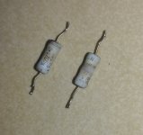
One channel blew the source resistors (0.56R). The 0.47R resistor still measures ok, but is discolored - pics attached.
Other channel did not have such issues but the voltage across the 0.47R source resistor was 1.04V - so the MOSFETs were biased at 2.2 amps 😱 So turned off power and will dial down the bias trim-pot before powering on again. By dialing down I am thinking of taking it to mid position - 12 or 13 turns for a 25 turn trim-pot. The trim pot is a 5k one. I recall Zen Mod advising to remove the MOSFETs - I can do that, but wary of damage to the PCB due to desoldering.
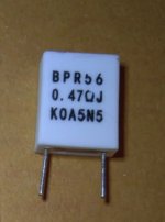
For replacement source resistors I am thinking of getting KOA BPR types.
Would appreciate advice / comments. Also, should I be checking something else?
However, all did not go well.
One channel blew the source resistors (0.56R). The 0.47R resistor still measures ok, but is discolored - pics attached.
Other channel did not have such issues but the voltage across the 0.47R source resistor was 1.04V - so the MOSFETs were biased at 2.2 amps 😱 So turned off power and will dial down the bias trim-pot before powering on again. By dialing down I am thinking of taking it to mid position - 12 or 13 turns for a 25 turn trim-pot. The trim pot is a 5k one. I recall Zen Mod advising to remove the MOSFETs - I can do that, but wary of damage to the PCB due to desoldering.
For replacement source resistors I am thinking of getting KOA BPR types.
Would appreciate advice / comments. Also, should I be checking something else?
Attachments
if you remove source resistor, most likely it'll be enough isolated mosfet so you can test it with diode/buzzer test is it blown or not - worry about short, not open one - open will show as non-biasable  - is that new word?
simple loogic was - IRFP150 is twice IRFP240 ........ back up that bias before powering on!!
now, as punishment - back up trimpots all the way down; confirm "down" with ohmmeter, do not think in CW-CCW terms if you don't have direction clearly marked
- is that new word?simple loogic was - IRFP150 is twice IRFP240 ........ back up that bias before powering on!!
now, as punishment - back up trimpots all the way down; confirm "down" with ohmmeter, do not think in CW-CCW terms if you don't have direction clearly marked
ZM,
Thanks for the guidance and sharing new word... 😀
I have ordered new source resistors. Will resume tweaking work (or should I say game?) when I have them in hand.
In the meantime will be in anticipation of BAF 2021 talks that are coming up...
- Z
Thanks for the guidance and sharing new word... 😀
I have ordered new source resistors. Will resume tweaking work (or should I say game?) when I have them in hand.
In the meantime will be in anticipation of BAF 2021 talks that are coming up...
- Z
Last edited:
if you remove source resistor, most likely it'll be enough isolated mosfet so you can test it with diode/buzzer test is it blown or not - worry about short, not open one - open will show as non-biasable
ZM,
Got new resistors, 0.47R 5 watt KOA BPR critters; source resistor on Q1 blown again...
Took out the MOSFETs also - Q1 shows connectivity on all 3 legs... it has become Dodo is my guess?
unfortunately, yes, if blinging beep anywhere
be happy - imagine that you did that, having precioussssss Semisouths inside

be happy - imagine that you did that, having precioussssss Semisouths inside
unfortunately, yes, if blinging beep anywhere
be happy - imagine that you did that, having precioussssss Semisouths inside
😀
Indeed. But with my miserly approach, I am willing to pay for SK170/SJ74 critters, but not Semisouths...
And are they even available nowadays?
Buy SemiSouths
You could try here, to buy SS.
Maybe he still has matched pairs
to sell.
michael.mazzola@impowersystems.com
You could try here, to buy SS.
Maybe he still has matched pairs
to sell.
michael.mazzola@impowersystems.com
ZM, F6 experts (well ZM is expert on everything ),
Since IRFP150s were giving "blinging beep" (become Dodo), decided to go back to IRFP240 that I had pulled out earlier from the same channel (amp was fully working for years then...).
After installing the IRFP240 in the PCB, fuses are blowing on power on. 🙁 Now scratching head...
Any specific position I should check for shorts or any other error?
),Since IRFP150s were giving "blinging beep" (become Dodo), decided to go back to IRFP240 that I had pulled out earlier from the same channel (amp was fully working for years then...).
After installing the IRFP240 in the PCB, fuses are blowing on power on. 🙁 Now scratching head...
Any specific position I should check for shorts or any other error?
Last edited:
... one of the first places to look at/check is the power fet to chassis insulation, maybe raised edge of metal thread hole, broken insulation washer, etc assuming everything in the power supply is working correctly.
- Home
- Amplifiers
- Pass Labs
- F6 Illustrated Build Guide