Jan, I am not into sim (I asked for a formula - aren't we engineers ?)
and I do not know what LMLTUFY is.
"My favourite programming language is solder " - not sure who invented this phrase ..
"I think it's the red and blue" , yes, I do not know, the curves are there but without
any description, so who knows ?
For me sim does not prove anything, but who am I to argue.
Let Me look That Up For You ;-)
Pretend you are looking at a scope. In the schematic, there is R1 and R4. On the 'scope' there is the current through the resistors, I(R1) and I(R4). R1 and R4 are different in value. I(R1) and I(R4) are the same in magnitude. QED.
Jan
Thx Terry,
So we can dismiss this equal load as something that caused confusion, but with the best possible intentions.
Equal resistors is the right way to go.
Hans
So we can dismiss this equal load as something that caused confusion, but with the best possible intentions.
Equal resistors is the right way to go.
Hans
Re post 11502 : in the meantime we have quite a few of schematics,
with different resistor designations, and it is not obvious which one
you are talking about. My scope reads voltages, no currents.
First mention of different resistor "legs" here was in a sim of Ricardo
as far as I can see.
I would love to see a specific justification for this choice, based on
formula and/or measurements, but maybe this is persistent.
Sorry Andreas, no disrespect intended, but I stopped spoon-feeding adult persons after my parents passed away.
The trail is in your own posts.
Jan
The trail is in your own posts.
Jan
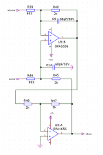
Or use this and enjoy both advantages.
Jan
Yes, for those preferring equal load for whatever reason this is a solution, but at the expense of an extra opamp.
A simpler solution would be a fully differential I/O amp like the perfect OPA1632 saving an extra amp.
Hans
.
Attachments

As_Audio,
I mixed you with 1Audio, so sorry for calling you Damian (which should be Demian 😀), but from Jan’s posting I understand you are Andreas.
Hans
I mixed you with 1Audio, so sorry for calling you Damian (which should be Demian 😀), but from Jan’s posting I understand you are Andreas.
Hans
Or use this and enjoy both advantages.
Jan
Yeah, that's a neat circuit. Half way between the standard 1xOPA bal IP
approach and a full 3xOPA instrumentation amp. I've seen it in a few mix
consoles.
If this was implemented with say 5532 or OPA2604, insert a 1k resistor
between U5A's + IP and gnd to address CM distortion. With OPA1656, prolly
won't make any difference.
TCD
Yes, for those preferring equal load for whatever reason this is a solution, but at the expense of an extra opamp.
A simpler solution would be a fully differential I/O amp like the perfect OPA1632 saving an extra amp.
Hans
.
The other option is use a VHQ, low Z, multifilar line output transformer driven
by 0 ohms source. You might be surprised how low the distortion is above a few
hundred Hz and how good they sound.
TCD
Please don't use 3602s until you have the ability to select device with more or less equal halves (they are not matched). My 2c
Please don't use 3602s until you have the ability to select device with more or less equal halves (they are not matched). My 2c
That is also my experience. For this and other reasons I gave up on them.
TCD
Please don't use 3602s until you have the ability to select device with more or less equal halves (they are not matched). My 2c
The specs state some form of matching, max 100mV between Vgss but the individual Idss are not specified, so may be anything between 30mA and 300mA ?
Joachim could make a simple test rig to measure Vgs at Id=20mA and show the results.
Hans
True. It’s important to understand how (integrated) analogue circuitry works. And I have learned something from that discussion.
I only had the impression that two different things were discussed here:
-the textbook differential amp (substractor) which has 4 equal resistors which represents equal common mode resistance in each leg, which is necessary for high CMRR
-and the approach with unequal resistors (1:3 ratio) in each leg which balances the differential mode input impedance. If this has any advantage for the audio signal I cannot say, but its an interesting variation of the circuit.
First, I do agree to Jan (one post earlier then the referred post)
Second, singe amplifier differential stages have 4 resistors (this is what you call 'the textbook differential amp'). The values of these resistors come from calculations the are intended to set the operating state of the amplifier (system). When the calculation is done for equal impedance it will result in different resistor values (up to 4 different values). The calculation done are just following from Ohm's laws. This is not about any fixed modules (like 1:3 ratio).
Third, there was only one subject (in this context) and that was 'differential amplifiers and amplification'
Last edited:
@Frans,
See pages 6.52 and 6.53 from Analog Devices.
https://www.analog.com/media/en/training-seminars/design-handbooks/Op-Amp-Applications/Section6.pdf
Equal impedance is important as seen from the opamps (+) and (-) inputs to reduces CM distortion.
Added and reinforcing to that, equal impedance values around a diff amp are needed to eliminate the effect of driving stage output resistances on CMRR.
I think that’s all there is.
Hans
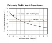
CM distortion is most noticeable with Fet imput opamps because of their varying input Capacity with common-mode input Voltage.
In this respect it’s worth mentioning the exeptional OPA 1642 which has a constant input capacitance independent of input voltage.
So CM distortion will be extemely low with this amp.
Hans
.
In this respect it’s worth mentioning the exeptional OPA 1642 which has a constant input capacitance independent of input voltage.
So CM distortion will be extemely low with this amp.
Hans
.
Attachments
@Frans,
See pages 6.52 and 6.53 from Analog Devices.
https://www.analog.com/media/en/training-seminars/design-handbooks/Op-Amp-Applications/Section6.pdf
Equal impedance is important as seen from the opamps (+) and (-) inputs to reduces CM distortion.
Added and reinforcing to that, equal impedance values around a diff amp are needed to eliminate the effect of driving stage output resistances on CMRR.
I think that’s all there is.
Hans
First, I am not contradicting any of that
Second, It depends on what you are doing, in the case at hand we have a (about) zero ohms output impedance source. And I do presume a modern opamp with low common mode problems of its ohm.
Third, defending against stray signals (e.m.) from outside the circuit is (today) also important, in that case the point of entry is important (e.g. the input side of the 'input'-resistors).
Fourth, just build and try, test and listen, have fun doing that and try to see the value of other systems (Ohm's low is still in effect).
Attachments
… I asked for a formula - aren't we engineers ? …
Maybe this will tickle your fancy....
Basically it is simple
In the example you have a circuit with an input impedance of 12k per side for a total differential input impedance of 24k (rIn) and a gain of 0.5 (G).
The lower 2 resistors R1 and R2 calculate as
R1 = (rIn/2) / (G + 1)
R2 = (rIn/2) / (G + 1) * G
where G is the gain (in this case 0.5) and rIn is the differential input impedance
The upper 2 resistors
R4 = rin - R1
R3 = R4 * G
Hope that helps 🙂
Last edited:
Sorry but you forget to include the source resistance Rsource.
With Rsource=0, cmrr is always perfect, no matter what resistances are used as long as they have the same ratio on both sides.
It is Rsource that changes this all.
Hans
But that is not fair, in the case at hand we can assume the source output impedance to be near zero, that was the presumption explained earlier.
And as also explained before, if this impedance is not zero then it's value should be subtracted from the input resistor(s) value.
It is important to remember what was said before, otherwise the context will shift and the value of the discussion is lost in the noise that results.
P.s. And sorry for the pause in the discussion, I have been a few days 'on the road'
Last edited:
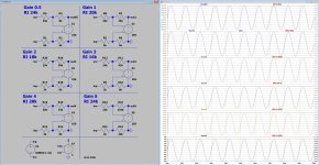
as, all, I have made a sketch for all four cases:
-common mode and differential mode
-equal resistors and unequal resistors 1:3,3 ratio
equal Rs: equal common mode input impedance on both inputs
Rs on the noninverting input 3,3 times higher: equal differential mode impedance on both inputs
There needs to be a differential voltage source at the differential inputs. Here in the example there are 2 voltages indicate (one on the + and one on the - input side of the amplifier).
Look at #11512 the I(inp)/I(inn) is always 1 (e.g. equal)
Last edited: