Gedlee I dont think the ideas of cutoff, I'm discussing, are for waveguides...the waveguide has no cutoff via its axial length vs Expansion and resulting mouth dimensions .... if I were to use cutoff for waveguide I would look to its width/height and where directivity falls off significantly...looking at FR the cutoff of the waveguide/compression driver system is simply the cutoff of the compression driver period.
I believe that it is crazy to think that horns have a "cutoff" and waveguides don't. This just reinforces to me why I never use that term.
The CD and waveguide as a system will yield the HP frequency location. It is not precisely that of the driver, the waveguide matters as well.
I've never heard the term 'direct energy measurement' used before and a search doesn't bring much up. The usual term is 'near field' for measurements very close to a diaphragm or port.
However, that doesn't apply equally to horns or waveguides where the wavefront is still developing at the physical mouth. The data you observe with a mic placement that close is likely to need a transfer function for the final segment or end correction to accurately represent the response at a listening position.
That applies even more for an off-axis measurement taken close to the mouth.
Of course you can do that; it's how the Klippel NFS setup works. It's pretty mathematically intensive though, and needs a lot of data points. If possible, I'd always advocate using 'nature's anechoic chamber'.
The basic concept is that your measurement should be taken once the system has transitioned to a point source (or line source) radiation, as this is then representative of where people listen.
I think the thing is that near-field is a relative term...
We called a certain monitor a nearfield monitor and Gedlee corrected us, saying it would more properly be a direct field monitor....same would go for measuring, no? Id have to find the post to give the details of direct field vs nearfield
To me it close the same thing...I call it a direct energy measurement, being very literal in that at the closest proximity, you will all direct energy, in the measurement, and non of the indirect energy
If you called it "Direct Field Energy" then it would make some more sense. But still not on the mark IMO. You'd really want the intensity (energy density) as that has a direction.
Sure you can compare one estimate of one horn to the other with the single point technique, but then you are missing the whole idea of directivity control, which is IMO the single most important aspect of any waveguide. Throwing the baby out with the bathwater so to speak.
At any rate, the software that I created did precisely what you guys are talking about. One could measure 13 Direct Field points (at any distance) with very good reflection rejection and then mathematically (magically!?) transformed it into far field data. It's not only doable, its been done.
I think the thing is that near-field is a relative term...
We called a certain monitor a nearfield monitor and Gedlee corrected us, saying it would more properly be a direct field monitor....same would go for measuring, no? Id have to find the post to give the details of direct field vs nearfield
To me it close the same thing...I call it a direct energy measurement, being very literal in that at the closest proximity, you will all direct energy, in the measurement, and non of the indirect energy
Direct field and near field are different concepts.
Direct field is when direct energy is greater than reflected/reverberant (indirect) energy.
The critical distance is where direct equals indirect, so direct field refers to anywhere within the critical distance.
So it's about in-room distance, and depends as much on the room as the speaker.
Near-field vs far-field is about speaker alone.
Near-field is when complete summation of all drivers, or all the paths from even a single driver or horn, has yet to occur. Mag and phase can vary greatly with only small mic movements. And -6dB per doubling of distance has yet to occur, which i think is the technical definition of the near-field to far-field transition distance.
Note group delay is a function of phase; near field has the strong potential to give bogus phase, and hence bogus group delay.
I get more convinced the more i learn, to toilet group delay...it's convoluted thinking created to held solve relative delay problems before digital delays, imho.
Just hear the Beatles sing "Phase is all we need"🙂
And a good dsp 😉
This vid from Erin is worth the time and might get help you on the right track re measurements and the near-field far-field stuff. Klippel's Near-Field Scanner vs Anechoic Chamber: Discussion with Christian Bellmann - YouTube
Yes your powers of prediction are truly a wonder. Getting the right answer for the wrong reason won't happen every time.Everything I predicted has come true so far. Based off of electrical impedance to start.
I see where you are coming from...as long you know when and when not to break the "rules"...no harm, no foul.
How about this...After viewing the group delay, what do you feel, you know about Marks horn, based off of it? Or do you feel that the group delay tells you nothing meaningful?
Mark100 has dozens of horns, the group delays they exhibit are not particularly meaningful, other than exhibiting another view of measurement data.
Every measurement is relevant....every measurement represents a unit of distortion or perfect, expressed in different ways.
Last edited:
Every measurement is relevant....every measurement represents a unit of distortion or perfect, expressed in different ways.
A good measurement would show the lake rises when we pee in it....
Relevant ??? 😉
In a real measurement of a driver and horn combined it is hard to separate out what is the horn and what is the driver. Comparison measurements of different drivers and horns can help give an idea what is coming from where. That is why a simulation is useful for analysing horns or waveguides, the "driver" can be perfect and show only what is coming from the guide.How about this...After viewing the group delay, what do you feel, you know about Marks horn, based off of it? Or do you feel that the group delay tells you nothing meaningful?
In mark's measurement the group delay gives a ball park estimate of the HP filter corner frequency and slope. Horns, waveguides and drivers by and large behave as minimum phase devices so there is no magic to be found in analysing the group delay.
A good measurement would show the lake rises when we pee in it....
Relevant ??? 😉
only 100%
having significant and demonstrable bearing on the matter at hand
Since our goal is to reach a destination, anything that is a step closer to perfect counts. I don't have to reference the concept of perception of group delay. One step towards perfect is another step away from the the threshold of audibility...and there's never anything wrong with that, where you draw the line and what to pay attention to and what not to, is your own personal business aka personal preference.
They used to say that 60fps was fast enough for video games and because our eyes have a "threshold" for the perception of movement near 60fps they thought it meant that it could be neglected as such....now in 2021 we have fps pushing hundreds of frames per second and 144hzrefresh rates to help keep up. I try to not to let peoples minds limit my intuition. Its been right too many times before.
Your analogy...the metaphor of "Pee" inspires me to think "insignificant amount"....right? A pee into a lake is such a small change...So in terms of group delay....small or large change is only relevant to the measurement we are analyzing and what it means to our sonic perception.
If we were talking FR than maybe a 0.5 deviance from 0 might be a pe in the lake.... and I too would want to see such sensitivity in my measuring devices because trends can show in subtle ways. If the deviance from 0 was 10db plus or minus....that hardly is a "pee" in the lake....so thus, unless you insinuate how much deviance in Group delay aka excess group delay? you are referring to as a "pee" I don't think you've what you think you've said.
Last edited:
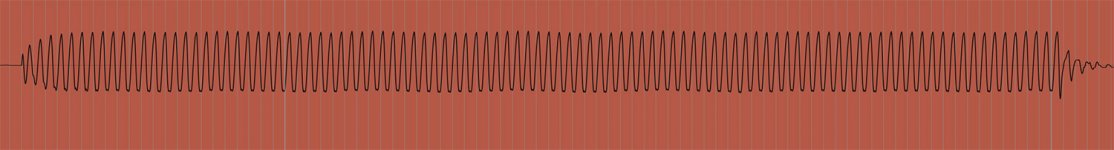
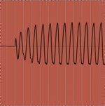
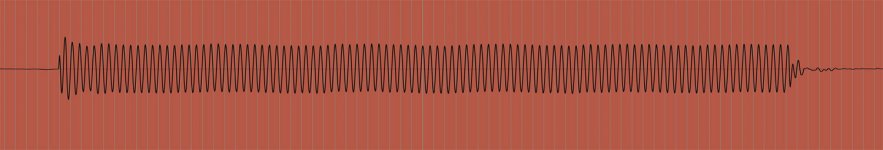
Compare 225hz (above) with ~6ms of group delay
with 294hz (below) with -763us
The amplitude takes time to reach a consistent level with 225 and 294 does not get there on the first cycle yet over shoots amplitude level almost immediately and balances off shortly after...
I saw what I thought I 'd see for the instance of 225hz.... attenuation to the of beginning of the initial signal lasting a few oscillations. I did not expect to see an overshoot within the beginning oscillations of the 294hz signal meaning to be a representative a low latency GD reading vs the example meant to be the opposite.
There were deviations from perfect among the first 21ms of both signal burst with the 294hz -763us GD being way more intense in the very first oscillations than 225hz 6ms GD
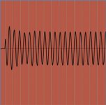
Below we have 400hz with a 3ms GD, the first ~3ms are selected.
So far these few experiments are evidence that GD is a distortion of the Amplitude Envelope, a term common to signal generators involving characteristics at the beginning, middle and end of a signal, based on key(input) press(start) and release(stop)....attack has to do with the very beginning of the signal, sustain is what the signal is doing as it is held constant and decay is whats done after input has stopped...The source signals are all intended to be perfect in amplitude, every oscillation...
Attachments


Last edited:
Camplo,
What you display looks like the result from a compressor. Rather than gd i would have concern about the driver under test being... an La2a or 1176!
What you display looks like the result from a compressor. Rather than gd i would have concern about the driver under test being... an La2a or 1176!
Last edited:
Is it you judging that your intuition was right 😉 The more I learn, simulate and measure the less I want to rely on my own intuition.I try to not to let peoples minds limit my intuition. Its been right too many times before.
6ms of group delay is quite a lot and implies a reasonably steep filter.
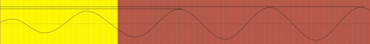
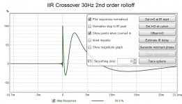
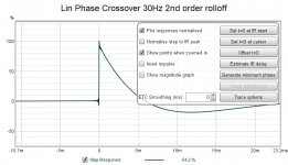
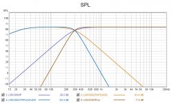
To demonstrate here are some synthetic impulses to show the difference between the HP rolloff by itself, crossed over to a woofer with a 2nd order rolloff at 30Hz and the same thing but with a liner phase crossover. 300Hz in this example.
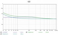
The group delay increase a little from the pure HP but that can be removed by making the crossover linear phase. You can see the difference in the step responses. The linear phase one will perform better in the sort of waveforms you showed above.
The group delay of the IIR version exceeds 1ms at 400Hz so it does fall into the sometimes could be heard if you time reversed the impulse from the research I showed before.
Attachments
Camplo,
What you display looks like the result from a compressor. Rather than gd i would have concern about the driver under test being... an La2a or 1176!
Thats what I've said numerous times...according to what my theory of what group delay is....it is a type of compression to beginning of the signal.....I said that....literally....several times in this thread.
A long time ago....Mark100 provided a study by a really respected person....this is the type of signal characteristics he showed in his demonstrations of group delay. The first time I seen it, I was like......I knew it! I didn't really know but rather, it was exactly what I thought group delay to be, though it was just a hypothesis at that time.
I also theorized that GD is the result of pressure in this instance...but not every instance that GD is sourced. To add to that theory, if you look at the troughs, they are all misshapen on the high group delay example....This is due to the idea that pressure is not equal in both directions because of the shape of the horn....When moving inwards....the shape of horn, to the diaphragm, is now tapered....carrying more air mass vs when the diaphragm moves outwards against an expanding line.
Attachments
Last edited:
Is it you judging that your intuition was right 😉 The more I learn, simulate and measure the less I want to rely on my own intuition.
6ms of group delay is quite a lot and implies a reasonably steep filter.
To demonstrate here are some synthetic impulses to show the difference between the HP rolloff by itself, crossed over to a woofer with a 2nd order rolloff at 30Hz and the same thing but with a liner phase crossover. 300Hz in this example.
The group delay increase a little from the pure HP but that can be removed by making the crossover linear phase. You can see the difference in the step responses. The linear phase one will perform better in the sort of waveforms you showed above.
The group delay of the IIR version exceeds 1ms at 400Hz so it does fall into the sometimes could be heard if you time reversed the impulse from the research I showed before.
The 6ms at 224hz is deep into the mechanical filter of the horn...Using electronic filters we can alter the shape of the FR though this area....but it is not going to do anything in regards to the pressure sourced GD located near cutoff of a loading horn.
Using tone burst I can also capture the decay characteristics. If look to the right of the tone burst you will notice the diaphragm does not instantly stop moving as the source signal does....350-400hz are is really where my horn show'ed some excess decay....I can see that decay on the tone burst recording as well...but it is not "severe" to my eye....I would need to experiment with tone burst to determine what my ear thinks it hears vs areas of really tight decay....
My take away was that with larger horns, the excess decay becomes much more of an issue...for example, the horn I am waiting for, around cutoff, decay will be much worse than what happens on my 350hz horn.
So even though I can use electronic filters to shape the response and possibly use the response close or even below cutoff....depending on the physics surrounding cutoff, results may vary.
Still excess decay/GD are an issue near the cutoff of the loading horn in this category. Avoiding this area leads to best sound quality.
I forgot my newly discovered issue of response through the high pressure areas nearing cutoff....The troughs are misshapen, as I put it, due to the line appearing tapered to the diaphragm as it moves inwards vs the expanding line the diaphragm see on outward motion....Am I the only one to discover this stuff? These are just theories as to the why but ya gotta start somewhere.
Attachments
Last edited:
Except a compressor ( if you doesnt manipulate sidechain) doesn't have freq involved... it look alike but not sure it is related!
And what about direct radiator and gd?
And what about direct radiator and gd?
It is a dynamic system...Q is only spec'd at F but we know it is not a static figure... Group delay is spec'd per frequency as well. A dynamic EQ is a compressor that is frequency specific =). You are speaking of a wide band compressor if we are to try and relate this to sound design tools.... The only relation I make to a compressor/compression, is that resulting signal btw.
I feel that we may be viewing signal compression, imposed on the diaphragm via pressure
I feel that we may be viewing signal distortion, imposed on the diaphragm via pressure
I do not know about direct radiator and GD...but I would first start with horn resp and look and see if there is any correlation to GD and pressure for that situation.
Lets research it!
Last edited:
- Home
- Loudspeakers
- Multi-Way
- Is it possible to cover the whole spectrum, high SPL, low distortion with a 2-way?