Thanks, X 🙂
It's a pretty weird recipe of multiple molding stages, material selection, vacuum, etc. and hand placement. Hand constructed with the aid of custom tooling, basically. Now that I have an idea of what the correct approach is, I'm confident I can achieve relatively complex and pristine parts. Hoping to see big improvements on the next attempts.
It's a pretty weird recipe of multiple molding stages, material selection, vacuum, etc. and hand placement. Hand constructed with the aid of custom tooling, basically. Now that I have an idea of what the correct approach is, I'm confident I can achieve relatively complex and pristine parts. Hoping to see big improvements on the next attempts.
Super cool. I'd be very interested in seeing progress pics or just more info in general - do you have a different thread or blog/etc?Thanks, X 🙂
It's a pretty weird recipe of multiple molding stages, material selection, vacuum, etc. and hand placement. Hand constructed with the aid of custom tooling, basically. Now that I have an idea of what the correct approach is, I'm confident I can achieve relatively complex and pristine parts. Hoping to see big improvements on the next attempts.
@mngnt, thanks-
No blog currently.
Created a thread on the iso panel progress here: https://www.diyaudio.com/forums/multi-way/375101-carbon-composite-panel-system.html#post6734617
No blog currently.
Created a thread on the iso panel progress here: https://www.diyaudio.com/forums/multi-way/375101-carbon-composite-panel-system.html#post6734617
Question for XRK971 -
For your TL design ( page 21, dated May 24th '20 )
Do you have a group delay curve you can show ?
I'd like to compare against the Purifi application note ( modelled in Hornresp ) and a simple MLTL I did with low port tuning that was not entirely successful.
Thanks !
For your TL design ( page 21, dated May 24th '20 )
Do you have a group delay curve you can show ?
I'd like to compare against the Purifi application note ( modelled in Hornresp ) and a simple MLTL I did with low port tuning that was not entirely successful.
Thanks !
I need to update this question now, having read various other postings on this thread and a good deal of the PMC-inspired TL thread !
What GD did you measure, and with what stuffing/damping scheme was that achieved ?
What GD did you measure, and with what stuffing/damping scheme was that achieved ?
PTT6.5X04-NFA-01 tested by Vance Dickason for AudioXpress Test Bench.
Test Bench: An Extended Home Audio 6.5” Midbass Transducer from Purifi Audio | audioXpress
Quoting the article:
"Figure 11 gives the inductance curve Le(X). Motor inductance will typically increase in the rear direction from the zero rest position as the voice coil covers more of the pole in a conventional motor, which is not exactly what you see in this graph. More important, the inductive “swing” from maximum inductance to minimum inductance from 10mm coil-in to 10mm coil-out gives a maximum inductive change of an almost nonexistent 0.009mH, which is nothing short of amazing and it is the lowest recorded inductive swing since Voice Coil started using the Klippel analyzer. Cheers to Purifi!"
Also a previously unseen image of the motor assembly and thoughtful discussion of its advanced design.
Question for XRK971 -
For your TL design ( page 21, dated May 24th '20 )
Do you have a group delay curve you can show ?
I'd like to compare against the Purifi application note ( modelled in Hornresp ) and a simple MLTL I did with low port tuning that was not entirely successful.
Thanks !
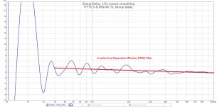
Hi IslandPink,
My measurements of the PTT6.5 and RS28F in a WG300 waveguide with the Harsch passive XO and TL yielded an average group delay of about 1.5milliseconds (I added a visual indicator straight line by eyeball to show the "average" value) at the 50Hz kickdrum frequency. It blows up at the corner tuning frequency circa 30Hz as expected as there is a round "knee" there and room modes dominate so it doesn't matter anyway. There are some wiggles and oscillations in the GD (+/- 2.5ms) due to a ripples in the frequency response. But the average group delay with 6 cycles FDW filtering to remove the effects of room modes. The number I like to look at is the difference between the GD at 100Hz and 1kHz. For this speaker, it is fairly low and indicates an excellent timing-accuracy between treble and bass.
Attachments
Last edited:
Thanks !
and 'wow', that's quite a lot different to a simulation of the empty TL.
Roughly what stuffing plan did you use to achieve this ?
and 'wow', that's quite a lot different to a simulation of the empty TL.
Roughly what stuffing plan did you use to achieve this ?
Anyone tried crossing this at 2.8khz and 3.2 kHz ? Thinking to get a used (cheaper) raal 70-10 to make mom instead of 70-20 which xrk used.
Last edited:
Thanks !
and 'wow', that's quite a lot different to a simulation of the empty TL.
Roughly what stuffing plan did you use to achieve this ?
Simple Passive Harsch XO Using PTT6.5 and RS28F in a Waveguide
Basically as described in the plans: line main rear chamber with eggcrate foam and one side of the remaining TL with one side. No foam on the final path to the exit. Add poly fill stuffing from closed end to the first turn. Increase stuffing density to taste. Measure impedance sweep and look for point at which the double peaks straddling bass tuning frequency start to combine together to look like an single “horned owl’s head with two ears”. Adding reticulated fish aquarium filter foam (large pore size) at the terminus can also be used tune the impedance peaks. Use this sparingly as it is very sensitive here. Maybe 1/2in thick at most.
Pretty cool that they managed to get the geometry such that the hard cone’s first big breakup is around 10Khz.
If we're being picky, Id argue its first breakup is 4200hz. And its got a bit of cone edge resonance suckout at 1200. But still damn fine for an al driver.
Can someone versed in the art explain the benefits of the Al cone here? I might be missing something but can't see it.
Yeah the original fibre mix cone is so good; I’m not sure I can see a big difference here. The HD2 and HD3 is a lower by ~5dB. The downside is the sensitivity is lower…
Last edited:
Thx. Except for sensibility, I dont see the advantage of this driver compared to other purifi regarding midrange ? Hence for active 3 way midrange, why would someone choose this one more than long stroke ?
- Home
- Loudspeakers
- Multi-Way
- Exploring Purifi Woofer Speaker Builds