What are the preferred LJM amps? Looking to replace a lm3886 so 50wpc and higher and 4/8 ohm compatibility.
I read the l12-2 was popular?
I read the l12-2 was popular?
What are the preferred LJM amps? Looking to replace a lm3886 so 50wpc and higher and 4/8 ohm compatibility.
I read the l12-2 was popular?
i thought the 20.5 was one of the highly popular ones, and measured extremely well
building one as we speak myself
It is. However it might be overkill for some users as well as expensive and difficult to mount compared to the L20SE. (Of course that depends on your chassis design.)
Also I don't care for the D1047 B817 at all since I have had too many fail. I don't think they are from a good supplier.
I much prefer the 5200/1943 in the L20SE.
The choice needs to consider many factors such as true speaker impedance (often not what the label says), speaker sensitivity, listening level, needed output power, chassis/heatsink design/style, etc.
i thought the 20.5 was one of the highly popular ones, and measured extremely well
building one as we speak myself
Isn't the 20.5 the one that keeps blowing up on people?
Mine blew up as did my MX50SE and MX50X2.
After switching to genuine Toshiba 5200/1943 nothing blew up. As a result I really don't like the D1047 and B817 that are used.
After switching to genuine Toshiba 5200/1943 nothing blew up. As a result I really don't like the D1047 and B817 that are used.

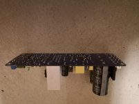
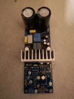
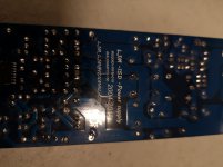
LJM-15D POWER SUPPLY MODEL
Hi all,
I Just purcase this module and wonder
If i can use thisone as a replacement for
a 150w subamp?
And how can i implement an auto on/off
function as seen on mostly every subwoofer amps
nowadays?
Hi all,
I Just purcase this module and wonder
If i can use thisone as a replacement for
a 150w subamp?
And how can i implement an auto on/off
function as seen on mostly every subwoofer amps
nowadays?
Attachments
Isn't the 20.5 the one that keeps blowing up on people?
haha, well thats concerning!
what seems to be the issue, thermal?
Hi all,
I Just purcase this module and wonder
If i can use thisone as a replacement for
a 150w subamp?
And how can i implement an auto on/off
function as seen on mostly every subwoofer amps
nowadays?
This works...
Project 38
Mine blew up as did my MX50SE and MX50X2.
After switching to genuine Toshiba 5200/1943 nothing blew up. As a result I really don't like the D1047 and B817 that are used.
I was told that the MX50SE that some of the small semi's don't have a very large SOA and I should use a 18-0-18 toroid. I built one with this voltage and It's good. I did use different final outputs though. Been working for month's.
Just my 2 cent's
Mine blew up as did my MX50SE and MX50X2.
After switching to genuine Toshiba 5200/1943 nothing blew up. As a result I really don't like the D1047 and B817 that are used.
I currently have 4 MX50X2 PCBs, none of the D1047s have skipped. Maybe the ones you got weren't good.
I put a 27-0-27v ac transformer and no problem.
Hard to say. For my MX50X2 one board blew and it was 2 shorted D1047 of the 2 boards x 4 = 2 of the 8 D1047 that went. For my L20.5 one board blew and it was 1 shorted B817 of the 2 boards x 8 outputs = 1 of the 16 outputs that went.
I am using 32-0-32 which should be no problem at all for the L20.5 (at least as claimed). So why did it blow on first power up? Before I could even apply a signal? My best guess is poor quality or fake outputs.
Yet my repaired MX50x2, MX50SE & L20.5 with Toshiba 2SC5200N & 2SA1943N are (so far!) rock solid. That is the L20.5 with only one pair installed in the output as a test!
There are a couple of other L20.5 owners in the L20.5 thread that are also having troubles. That really should not be the case with the L20.5 or L20 8 output (4 pair) amplifiers.
Last edited:
Hello Kozard,... multiple boards blew...
It appears we are experiencing the same problem with components that can not survive virtualy anything. I also have qute a few Toshibas and NJW1302/3280 but will refrain from placing them into any of these dissapointing boards.
Ashes to ashes, dust to dust.
I am also loking forward to build the Blameless Amplifer, and I know where to seek. It appears that Mr. Douglas Self is planning come-back with reviving Signal Transfer company and also plans to make his boards and kits available.
Meanwhile, read a review on the link below of Douglass Selfs Trimodal amplifier at this Italian site (in English). Enjoy.
[Review] Trimodal amplifier - listening test - [English]
It would be very nice to get designs that are done right and with correct layout.I am also loking forward to build the Blameless Amplifer, and I know where to seek. It appears that Mr. Douglas Self is planning come-back with reviving Signal Transfer company and also plans to make his boards and kits available.
Kits with quality components would be nice too.
Sadly I have not saved much time or effort with the kits that I have bought so far. I don't do my own design and board very often but I have found that in the end it takes the same amount of time as many kits and ends up better. The problem is that the kits give the illusion of saving time and effort. (And then you end up needing to fix it and sometimes the end result is pretty mediocre.)
I have this one, although I cannot vouch for its accuracy. If you do not wish to buy from China, there is this company in France: https://www.audiophonics.fr/en/ampl...fier-boards-150w-8-ohm-mono-pair-p-10314.html. There are a few comments on the chosen components there, too.
Attachments
Thank You for interesting but hmm, I think this is not a circuit diagram from this amplifier L15 because looking fast I see 2 differences, on circuit are all power transistors N channel and circuit have inductor and amplifier physicaly have power transistors N and P channel (IRFP240 and IRFP9240) and have not inductor on board.
You guys should try the Pass AB100 ,wonderful amp . Latest Prasi schematic works extremely well .
Who needs another transistor power amp these days?You guys should try the Pass AB100 ,wonderful amp . Latest Prasi schematic works extremely well .
- Home
- Vendor's Bazaar
- LJM Audio