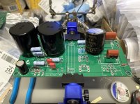
Started a verification build on the boards kindly supplied by Vunce and XRK tonight. Here are some photos of how the board is coming together. I have not applied any power yet so I can’t comment on it working just yet. IMHO, a few things I notice about the board and layout are:
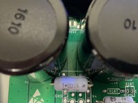
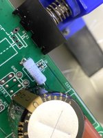
1. The room for the 22,000uf filter caps crowds the space for R105.
2. The holes for the 22,000uf caps are a tight fit. Maybe not the usual diameter for snap-in caps?
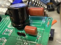
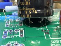
3. The output cap, C124, could really use a lot more real estate. I’m using a 4,700uf 35v Nichicon KG, which is a 10mm snap-in cap. So the leads don’t fit the board, which is 7.5mm lead spacing I believe? And a cap this size starts to bump into R127.
Overall, seems like a great layout JPS64. Just adding my two cents. Hope these comments help. Thanks to Vunce, XRK and JPS64 for the design, layout, and including me in the process!
1. The room for the 22,000uf filter caps crowds the space for R105.
2. The holes for the 22,000uf caps are a tight fit. Maybe not the usual diameter for snap-in caps?
3. The output cap, C124, could really use a lot more real estate. I’m using a 4,700uf 35v Nichicon KG, which is a 10mm snap-in cap. So the leads don’t fit the board, which is 7.5mm lead spacing I believe? And a cap this size starts to bump into R127.
Overall, seems like a great layout JPS64. Just adding my two cents. Hope these comments help. Thanks to Vunce, XRK and JPS64 for the design, layout, and including me in the process!
Attachments
-
 0286F279-8192-4A2E-8C86-D20845B3770C.jpeg344.7 KB · Views: 347
 -
 F48BFE3A-3302-4897-A2B5-5A477583B0C0.jpeg213.3 KB · Views: 347
 -
 05FC6193-0BD1-4B21-A6A0-E7B4685F4462.jpeg296 KB · Views: 337
 -
 8C8A744F-3AC4-4319-ABCE-B8254557F074.jpeg282.8 KB · Views: 324
 -
 BC9D6985-0989-4C8F-92E6-DA566D7C2ED2.jpeg259.2 KB · Views: 327
@jwjarch
Please use suggested parts from the BOM and they´ll fit.
4700µ/35V --> dia. 18mm, RM7.5mm --> UFW1V472MHD
22000µ/25V --> dia. 30mm, RM10mm --> ELH229M025AS4AA (1.5mm holes as specified in the datasheet)
0R22 --> BR58 Series (BPR58CR22J in schematics)
All parts are available at mouser, especially take care about that point during layout.
JP
Hi JPS64,
I think we know that you do choose the sizes carefully during layout, and thank you for fixing us such a fine layout. It’s quite compact and beautifully done. I think what Jwjarch is pointing out because he is using what’s typically already available on the bench, perhaps we can modify the final layout to be a bit roomier for more options. Indeed I have a lot of those bigger snap in caps myself.
Jwjarch,
Thank you for assembling the first build here - looking forward to seeing how it works.
Cheers,
X
nichicon KG typically available on the bench? More expensive then MUNDORF Audiograde ones!
On one side trying to save money on the choke, on the other side... Well, seems I´m to old for that.
JP
On one side trying to save money on the choke, on the other side... Well, seems I´m to old for that.
JP
Hi JP. I just want to apologize for any perceived negative comments I made about the layout. I know you certainly do your homework when it comes to parts selection and size was definitely a concern here. I was looking at it from a different perspective is all.
To X's comment, I was using what I had available in my parts drawer. The PSU filter caps in particular are the most commonly used for First Watt PSU boards, so I wanted to see if accommodating a 35mm dia cap would be possible. I am interested in helping and finding alternatives for parts based on my experience with past projects. All too often we all go to Mouser, Digikey, etc. and find parts out of stock, especially these days with the supply chain all out of whack. You never know when the stock of 562 capacitors that are there today will be gone tomorrow. I just wanted to point out that there may be a few small tweaks that could allow for a few different sizes of components. Just my two cents.
As for the Nichicon KG's, I purchased them when I was intending on just wiring point to point for this build. I wouldn't normally have such nice parts on hand at all times. 😉
So thank you JP for the beautifully laid out PCB's. Your talents and skills are, no doubt, a huge part of what makes this forum so great. This is probably my 6th or 7th set of your boards that I have worked on, going back to the ALPHA 20W pcb's. I really appreciate all you do for the community. Again, I sincerely apologize for any offense.
@jwjarch
I´ve to apologize. I´m trying unsuccessfully to simulate CC/CV heater regulator circuit for 300B. I don´t know what is wrong, but I´ll find out! So I´m really annoyed. It´s working in my head but not in simulation. Well, time for a deep politic correct espresso.
I hope that the coming test will be more successful and that you enjoy what you´ve built.
JP
Thanks JP. I'm looking forward to updating everyone once I get some power to the first board. Hopefully tonight.
Good luck on your 300B project! That sounds exciting. Is this for diyA?
Good luck on your 300B project! That sounds exciting. Is this for diyA?
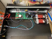
Hello all . I am about to jump in too. I had everything nearly ready to assemble with point to point and X was kind enough to share a set of boards from Vunce with me. My intent is to use things I have lying about in my parts bin too and I have a Vicor-flatpack smps power supply
I had to switch gears with my heatsinking plans with the boards but it promises to be a very cool ( hot ) and heavy project.
..dB
I had to switch gears with my heatsinking plans with the boards but it promises to be a very cool ( hot ) and heavy project.
..dB
I put together a mouser BOM based on the specs in the BOM , hopefully this works
Link to Mouser BOM - for one channel
Link to Mouser BOM - for one channel
First channel is up and running. The cap multiplier circuit is working great to slowly ramp up power from the SMPS laptop PSU I’m using. It’s a 19.5v HP laptop supply. Voltage after the second filter cap is 13.1v measured at R107. I didn’t run it for long, but temps did not climb much on any components. I played a few seconds of music from a Bluetooth receiver directly in to the amp through my usual dual 3fe-25 mini-k test speaker. Sounded really good even though max volume is very limited with just the Bluetooth receiver. One of the best parts, I couldn’t even tell the amp was on even with a relatively high sensitivity speaker. It’s so quiet! I will plan on getting the second channel together very soon. Nice work JP and X! Seems to me the circuit is working perfectly!
Attachments

Last edited:
I think that would be great for mounting JP. The placement of the LU, resistor, and IRFP240 are a leftover from my previously planned point to point build, hence the flying leads. It would be nice to get rid of those and clean things up a bit more.
One more note. I used a nylon stand-off at the corner of the board with the PE connection. I was worried about prematurely grounding the board to the chassis rather than the star ground and creating a ground loop. Am I over thinking it?
One more note. I used a nylon stand-off at the corner of the board with the PE connection. I was worried about prematurely grounding the board to the chassis rather than the star ground and creating a ground loop. Am I over thinking it?
Last edited:
Hi X. I plan to do a LuFo Lite when the PCBs are available - the least I should do having asked the original question about a lite version of the LuFo!
I don't really need another headphone amplifier so my use case will be my 15R Lowther speakers, with bias current around 1.5-1.7A.
As I already have some, I would like to use the Triad inductors I linked to a few posts back, which should be good for 2A DC current, though inductance is a bit low at 35mH - any thoughts?
https://www.diyaudio.com/forums/hea...tor-se-class-headphone-amp-4.html#post6756315
For the target bias current I'm assuming a total load resistence of around 1R0 - 1R2 - with the choke DCR of 790mOhms that means an additional resistor of around 0R2 - 0R4.
For the power supply I have a spare toroid with two 12VAC 5A secondaries - if I hook them up to LT4320-based rectification the LuFo Lite Cap Mx will see about 17VDC so around 13VDC at the LU1014D. The toroid seems quite small but if I assume a 1.7A bias current the draw on each secondary will be around 3A so well with load spec. and as the amp is running in class A the current draw should be pretty much constant.
Thanks again to you and JPS for pushing on with this development and to the guys who are doing the test builds.
Great work, Jwjarch! Glad it’s playing music and is quiet. It was meant to be a headphone amp so has to be absolutely silent with no music playing. I am surprised the voltage is only 13v after the cap Mx, what is the drop across the CRC? If it’s not that warm, you could probably use a 24v SMPS for more headroom. Just try to keep the voltage after the CRC below 20v. The dual speaker inductors look perfect for the job (low profile).
Thanks!
Thanks!
Hi NB,
Your plan outlined above sounds perfect. I think 35mH can work - it depends on how it’s measured as that is an average value at some frequency. For example, the custom inductors I ordered were 60mH but the company spec’d that at 10kHz (where you really don’t need that much inductance as the current is fairly low for music content there). Where you need it is for bass and it measures 160mH at 20Hz. So I think you might be fine if the spec is for say 1kHz or 10kHz. But for super high sensitivity Lowthers I don’t think you need much current.
Your plan outlined above sounds perfect. I think 35mH can work - it depends on how it’s measured as that is an average value at some frequency. For example, the custom inductors I ordered were 60mH but the company spec’d that at 10kHz (where you really don’t need that much inductance as the current is fairly low for music content there). Where you need it is for bass and it measures 160mH at 20Hz. So I think you might be fine if the spec is for say 1kHz or 10kHz. But for super high sensitivity Lowthers I don’t think you need much current.
- Home
- Amplifiers
- Headphone Systems
- LuFo Lite - a 1 Transistor SE Class A Headphone Amp