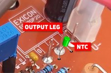
I think this leg will be much colder than the transistor die.
In your example the good thing is that thermistor is soldered to the pcb, no wires needed.
I'm planning to glue it directly to the metal heatsink (metal tab) of the transistor, on its side.
I think this is the spot that's 'closest' to the die, and therefore it's temperature is also closest to the die temperature.
Attachments
Last edited:
Not bad, but not as good as HEXFET version.
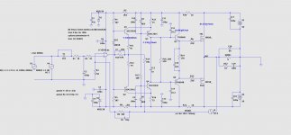
Just a question, to check my own understanding:
Does the flow go:
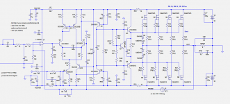
1. Input to opamp non inverting
2. Output of opamp goes to common base voltage amp
3. Output of common base voltage amp goes to another common base voltage amp
4. This follows into normal driver into output device
Is this about right? More wondering if I'm right about the common base into common base stuff. Thanks.
Attachments
Just a question, to check my own understanding:
Does the flow go:
1. Input to opamp non inverting
2. Output of opamp goes to common base voltage amp
3. Output of common base voltage amp goes to another common base voltage amp
4. This follows into normal driver into output device
Is this about right? More wondering if I'm right about the common base into common base stuff. Thanks.
@drinkingcube The grounded base topology is very fast, Cob being put out of the running, Cbe is much smaller, and does not suffer from the Miller effect. Its current gain less than 1. It offers high isolation between the input and output results in little destructive feedback and high stability. So it's a great I/V converter. The only drawback is that it has low input impedance that's why we need opamp as a buffer at input. Sounds very clean, smooth and tube-like.
@minek I think it would be necessary to make an explanatory diagram to illustrate how this unique topology works. I would mark the HiZ and LoZ nodes and current and voltage conditions on it. I might ask for your help making this.
Last edited:
>explanatory diagram to illustrate how this unique topology works
Well, that would be great...
Some help could be provided by original articles describing these amps:
1) Original Wiederhold's article + crude translation
2) Original article (Lomakin and Parshin + crude translation
All relevant articles zipped and attached here.
And of course lengthy discussions in this thread.
That's where it all started 🙂
Maybe the best starting point would be to translate these articles correctly, and understand them?
My Russian is as good as my German 🙂 Some basics from 30 years ago...
Attachments
Last edited:
Thank you minek. I'll try my best. Based on my limited knowledge I could also say we use 4 regulated CCS' as VAS here. The first regulated CCS regulates the second one.
Last edited:
Wow that is very interesting. Zin for each common base is re = 1/gm? EDIT: how is gain set? I see on wiki that the gain is gmRc, is Rc the input impedance to next common base in parallel with the 75 ohm resistor?@drinkingcube The grounded base topology is very fast, Cob being put out of the running, Cbe is much smaller, and does not suffer from the Miller effect. Its current gain less than 1. It offers high isolation between the input and output results in little destructive feedback and high stability. So it's a great I/V converter. The only drawback is that it has low input impedance that's why we need opamp as a buffer at input. Sounds very clean, smooth and tube-like.
@minek I think it would be necessary to make an explanatory diagram to illustrate how this unique topology works. I would mark the HiZ and LoZ nodes and current and voltage conditions on it. I might ask for your help making this.
More wondering if I'm right about the common base into common base stuff.
Some go even further... 🙂
Attachments
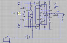
... now that ... that is hard to follow 🙂😱
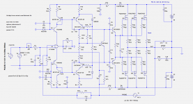
Just an example of possible further development. Some Russian diyers want to take this topology to the extreme. 🙂
This might be next (3rd and 4th in line of planned amps)....
At least we are reaching slew rate about 100uV/s, and keep everything very stable.
At least we are reaching slew rate about 100uV/s, and keep everything very stable.
Attachments
Last edited:

This might be next (3rd and 4th in line of planned amps)....
At least we are reaching slew rate about 100uV/s, and keep everything very stable.
That second diagram looks like the Alexander amplifier, but improved with cascodes and multiple feedback. Interesting. I might try this one out with a BJT output stage
Why BJTs? What's wrong with mosfets?
I have the BJT's 😉 My target output power is a lot lower too.. only 35-38V rails with the transformer and chassis i have in mind. I have some NJW3281/NJW1302 i would like to use.
In this case it would be nice to use output triplets.
So OS would change to triplets, and Vbe multiplier should be changed to 'normal' one, without thermistor.
So OS would change to triplets, and Vbe multiplier should be changed to 'normal' one, without thermistor.
In this case it would be nice to use output triplets.
So OS would change to triplets, and Vbe multiplier should be changed to 'normal' one, without thermistor.
Yep, I am a fan of triples 🙂 Probably going to use Diodes Inc DZT5401/DZT5551 parts predrivers, MJE243/253 or the Toshibas for drivers.
- Home
- Amplifiers
- Solid State
- HexFet Amp Based on Philips AH578 and LMK