nounouchet,
Thank you very much for your interest in informing us ..
This is a good news in relation to the worst. My best wishes for a speedy recovery Olivier!!
Thank you very much for your interest in informing us ..
This is a good news in relation to the worst. My best wishes for a speedy recovery Olivier!!
Last edited:
Greg , thank you for your explanation...
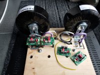
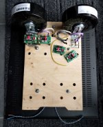
This circuit with the two fans after monitoring keeps the temperature of the heatsinks constant at 43 degrees Celsius with the temperature in the housing of the mosfet at 55 degrees Celsius .... I have seen my amplifier rise to 52 degrees in the heatsinks I guess in transistor housing definitely 60 plus degrees Celsius .
I believe that everything inside the amp will work more comfortably in such a low temperature of about 43-45 degrees ....
I will place it inside this circuit maybe together with a converter step down 24V to 12V like this....DC DC 5 32V to 12V3A Automatic Voltage Stabilizer Power Converter Regulator Dropshipping|Voltage Regulators/Stabilizers| - AliExpress to power it from the main power supply, I hope it does not affect the sound of the amplifier, since the auditions are over two hours each time and I want to not worry about the temperatures in summer.
Nikos,
Do what you think is appropriate but these devices running in the mid 50c range is perfectly acceptable for many, many years.
Just because it feels uncomfortably hot to us humans, the devices are far below their design limits.
I actually run a First Watt F4 in a small 3U and it gets way hotter then that.
Cheers,
Greg
Hi Danny_66
Better late than never😉
I am glad some peoples try out other versions than the USSA-5.0.
Is it original version 3 or 3.1 or 3B?
So you are using an “ideal “bridge for your PSU with well regarded Toroidy transformers. This is a good start. 🙂
For the amplifier pcbs do not hesitate to ask for questions - if any.
Thanks for sharing.
Fab
Hi Fab,
Yes, fine tuning my speakers took some more time than expected, as always 🙄
It is the original 3, since I already have the input jfets and mosfet drivers.
I have the USSA-3.3 2018-06-25 manual rev 0.6p, is this still valid ?
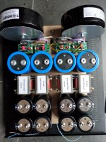
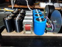
An "ideal bridge" is really a free lunch, no voltage drop (so no heating) and no switching noise.
Really ideal for class-A low voltage, high current.
Now everything PS related is screwed in, next is the wiring.
Danny
Yes, fine tuning my speakers took some more time than expected, as always 🙄
It is the original 3, since I already have the input jfets and mosfet drivers.
I have the USSA-3.3 2018-06-25 manual rev 0.6p, is this still valid ?
An "ideal bridge" is really a free lunch, no voltage drop (so no heating) and no switching noise.
Really ideal for class-A low voltage, high current.
Now everything PS related is screwed in, next is the wiring.
Danny
Attachments

I actually run a First Watt F4 in a small 3U and it gets way hotter then that.
Hello Greg,
Any problems/downsides to running your F4 in a 3U? Any precautions to take?
The diyaudio store recommends 4U for almost every amp build but its heft is a problem for me so I was wondering...
Cheers!
Finally I started to do some soldering on the USSA-5 pcbs - I follow the instruction from the very good manual of Fab and get some outstanding support from a very nice diyaudio member via e-mail and skype. 🙂
I've to say that this is my first amp project.
Ordered the chassis directly from modushop - as I'm doing dual mono with two SLB psu so I need some space... there is a summer sale at modushop for a week - fyi!
I've to say that this is my first amp project.
Ordered the chassis directly from modushop - as I'm doing dual mono with two SLB psu so I need some space... there is a summer sale at modushop for a week - fyi!
Attachments
I've to say that this is my first amp project.
Take your time to build as per Fab's instructional manual.
It will reward you later, musically!
It's an awesome amp.
I am gathering parts for a USSA-5 build. I am planning on using the SLB (Smooth Like Butter)power supplies in dual mono. I am considering the Antek AS-4222 transformers that are rated @ 22V. What would be my DC output from the SLB if I choose to use the transformers? What is the final desired DC output voltage for the USSA-5? I read that the SLB has an additional 3V drop as compared to a more traditional supply.
AS-4222 - 400VA 22V Transformer - AnTek Products Corp
AS-4222 - 400VA 22V Transformer - AnTek Products Corp
tmas,
For dual mono power supplies, 2 units of the 300VA unit or even the 200VA unit should be sufficient.
For dual mono power supplies, 2 units of the 300VA unit or even the 200VA unit should be sufficient.
Tmas
As zman is indicating, 200 to 300 VA per channel would be enough.
For the PSU voltage +/- 23 to +/- 27 VDC is optimal for the USSA-5.
For example, 27VDC if you have bigger heatsink and 23VDC for smaller one. You need high bias current for class A operation thus a lot of heat to dissipate. 25 Wrms in class A needs twice the bias current for 4 ohms than for 8 ohms speakers. The good thing is that the very low source resistor value (0.05 and newly 0.02 ohms) increases the class A enveloppe for higher power.
For the proper transformer voltage I know that the SLB uses an ideal bridge which normally allows higher output dc voltage but since it also has a series regulator and a resistance between the main caps there will be a voltage drop which can be adjusted I think but limited to the max current drawn. You are better directly asking XRK member how to estimate the voltage drop.
Good continuation
Fab
Last edited:
I'd say a transformer with 21 VAC secondaries is about right if you want to use a SLB with the USSA5.
Hi Tmas,
During my USSA5 build I used an Antek AN-2222 trafo with an SLB psu for the initial power-up, this combo was good for 26vdc under load. For my final assembly I used a pair of AS-3224 trafo’s with dual SLB’s, this combo yielded 27.5vdc@1.3A bias. My heatsinks are very large and handle the increased voltage without a problem.
If you planned your chassis with borderline heatsink size, I’d recommend a pair of 20v Antek trafos. If your HS are capable, a pair of 22v trafos should work great with a little extra OOMPH! 😀
Good luck with your project, this is a wonderful amp Fab shared with us.
Cheers,
Vunce
I am considering this 4UX400mm chassis.
Dissipante 4U – diyAudio Store
Would the heat sinks be sufficient to run the higher rail voltage 27V as described by Vunce?
Is there any practical or audible up/down side of choosing a larger transformer say 400VA verses 300VA?
Dissipante 4U – diyAudio Store
Would the heat sinks be sufficient to run the higher rail voltage 27V as described by Vunce?
Is there any practical or audible up/down side of choosing a larger transformer say 400VA verses 300VA?
Last edited:
tmas,
Since both 300VA and 400VA transformers for each channel are adequate for your application, there should not be any audible upsides or downsides.
Off the top of my head, a few "practical" downsides of using larger transformers are additional weight, (often) additional space required, and greater inrush current at the time of power on.
I recall Vunce using larger and taller heat-sinks - his chassis was custom build. The amount of heat dissipated will be dependent on your biasing (how many amps) and rail voltage. For example, with 1.3 amp bias and with +/- 27V rails you should be dissipating around 70 watts per channel, and the heat-sinks of the Dissipante 4U x 400mm chassis should be adequate, assuming your ambient temperature is within 30 degrees Celsius.
Last edited:
Hi Twocents
With such a small change it will only increase the amplifier gain slightly (from 10 to 11 for example) thus no big deal. I use all the same gain for all my USSAx class A amplifiers.
You can now see my “PR” smile 😉
For the 5B, read the very important note at the end of the manual about the output transistors pin out connection to the pcb…
Good luck
Fab
Last edited:
Hello FAB,
I am looking at a pair of Coincident speakers for my system to be used with my Atma-Sphere M-60 kits that I built and eventually the USSA-5. The speakers are 14 ohms 10 ohm minimum impedance and 92 db efficiency.
I was browsing your home page and saw mention that the USSA-5 is for use with 4-8 ohm speakers. Would the higher impedance Coincident speakers be a problem for use with the USSA-5?
Hi tmas
The mention on my home page is only to indicate that it is suitable for the majority of speakers which are nominally 4 or 8 ohms. Maximum higher impedance is not a problem at all. In fact your speakers impedance makes them a very easy load for amplifier.
Fab
The mention on my home page is only to indicate that it is suitable for the majority of speakers which are nominally 4 or 8 ohms. Maximum higher impedance is not a problem at all. In fact your speakers impedance makes them a very easy load for amplifier.
Fab
Last edited:
- Home
- Amplifiers
- Solid State
- USSA-5 Build with Review