The Monkey Coffins sing really well with the USSA-5...
Matthias,
I've been looking at the OSMCs a lot recently... 😀
Last edited:
Matthias,
I've been looking at the OSMCs a lot recently... 😀
Me too, but I also keep a close eye to the OSMT
Open Source Monkey Tower
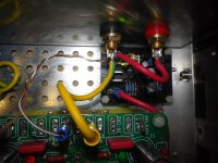
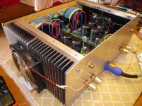
After a long time, I was finally able to complete fabulous FAB USSA-5 amplifier. First of all, many thanks to FAB, not only for this design and boards, but also for excellent QOS and his willingness always answer the questions, even though they could be asked many times by many members before. Many thanks to other members for sharing their knowledge and inspiration as well. Here you can see some photos of my amp.
Hi Amadeus00
You are very welcome 🙂
This is an exquisite built for sure.
 your amp clean construction is a lot better than mine.
 What bias current have you used for final adjustment? With these heatsinks you can go up to 2A with +/-24VDC supply!
One tip is that you probably could have a visual mean to differentiate between V+ and V- wiring from psu to USSA pcb since they are the same colour. That may prevent connection mistakes 😉
As for the speakers they are probably good for their category but based on your well regarded DAC you definitely should consider a speaker upgrade to get the best of the source and amplifier combination...and of course a DC protection for your speakers.
Keep us posted on your impressions after the break-in.
Thanks again for sharing your build pictures.
Fab
Last edited:
Ηello Fab.
For a long time I wanted to ask the following: since the temperature here in Greece go up sharply to 28 C degrees of room, and I get 48-50 C degrees on heatsink in my amplifier.
What is the safe temperature in degrees C value that mosfets should reach their housing ? my bias is 1.3A heatsinks are 28cm x 15.5cm x 4cm .
Also s there anyone who has tried to use it as a CRC vs a capacitance multiplier (CFP topology) power supply any comment ?
Thanks.
Last edited:
Hi Amadeus00
What bias current have you used for final adjustment? With these heatsinks you can go up to 2A with +/-24VDC supply!
Fab
Hi FAB,
I am using 1,1A bias current. It is my first proper Class A amplifier and to be honest I was a little bit afraid of the temperature. Lower temperature should be better for transistor lifetime. I am using TOROIDY audio grade toroids, 2x19 VAC which provides something 27,5VDC without any load. If I decided to increase bias current to 1,4A or 1,5A, would it have also impact on sonic performance?
Fab, could you explain to us what will happen if the temperature exceeds the maximum allowable limit ...
I see that from a temperature onwards it starts gradually and decreases the bias..
I see that from a temperature onwards it starts gradually and decreases the bias..
Last edited:
Hi NikosΗello Fab.
For a long time I wanted to ask the following: since the temperature here in Greece go up sharply to 28 C degrees of room, and I get 48-50 C degrees on heatsink in my amplifier.
What is the safe temperature in degrees C value that mosfets should reach their housing ? my bias is 1.3A heatsinks are 28cm x 15.5cm x 4cm .
........
Thanks.
Don’t wait too long 😉
The parameters you have used are quite correct. Semi-conductors generally can reach up to 150C internal for destruction. Of course at the package body the temperature is less than that. An audio amplifier with reasonable expected good service life should last at least 30 years or more (excluding the electrolytic caps of course). Lower temperature extends life but really < 60-70C at the transistor body is not a problem. Normally with main heatsink being <=50C the transistor body should easily be <60C unless you have a bad interface ( non linear surface and/or missing grease, or inefficient pads).
Fab
Hi FAB,
I am using 1,1A bias current. It is my first proper Class A amplifier and to be honest I was a little bit afraid of the temperature. Lower temperature should be better for transistor lifetime. I am using TOROIDY audio grade toroids, 2x19 VAC which provides something 27,5VDC without any load. If I decided to increase bias current to 1,4A or 1,5A, would it have also impact on sonic performance?
Hi Amadeus00
As per my response to Nikos, you will probably not live long enough to see the end of the output mosfet used in normal operation at <50C...😛
You should be able to get easily 1.8A with your PSU. However, it depends on the quality of your main transformer but your Toroidy should be fine ...
Lateral mosfet reduces the bias as Tempe increases when current > about 130ma. So no risk there. The thermistors are used for the driver’s temperature compensation.
1.1A is sub-optimal with your actual heatsink. Class A amps have lower THD with increasing bias current (especially mosfet). Higher bias can allow you to stay deeper in class A region at high power and/or low impedance of speaker at specific frequencies. Also, increasing the output bias in that topology means increasing input stage and output stage respective gain which increases the damping factor. Depending on your speakers and taste you may prefer either a lower or higher damping factor. In any case, the USSA-5 damping factor should stay in the “good” range for an home amplifier.
You can always try it out to see what suits you best but do not worry about breaking something if you stay < 2A bias.
Fab
Last edited:
Fab, could you explain to us what will happen if the temperature exceeds the maximum allowable limit ...
I see that from a temperature onwards it starts gradually and decreases the bias..
Hi again Nikos
See my previous responses about temperature management. You are right about output lateral mosfet.
As clearly stated in the manual you should install a thermal switch on the main heatsink that disconnects the main AC line supply in case of high temperature due to failure for any reason. I personally use 60C setting for that purpose.
So far it has helped me once with a modified Hiraga Super Class A amplifier with bjt outputs...
Fab
Many thanks Fab ...
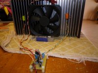
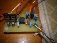
I try to manage the temperature with external fans through a processor which will start starting at 5 volts completely silently the start is programmed internal chip at 45 C
I try to manage the temperature with external fans through a processor which will start starting at 5 volts completely silently the start is programmed internal chip at 45 C
Attachments

This is my preferred method to assess heatsink temperature:
In other words: as long as I can keep my fingers on the heatsink for a while, I don't even think about it 😉
Blimey hot is 10 seconds hands on = 45 deg C.
Crikey hot is 5 seconds = 50 deg C.
Bloody hot is 2 seconds = 55 deg C.
X*?@! is 60 deg C.
All of these are within an acceptable range, although
X*?@! is resrved for the more mature constructor.
In other words: as long as I can keep my fingers on the heatsink for a while, I don't even think about it 😉
Fab, could you explain to us what will happen if the temperature exceeds the maximum allowable limit ...
I see that from a temperature onwards it starts gradually and decreases the bias..
Nikos,
Many people of have asked this question. I'm in Arizona and as you can see from my build mine is in a small 4U chassis. In the summertime it regularly hits 43+ here. My listening room is surrounded by courtyards and a large garage that heats up to 50c. My chassis temps are usually in the upper 50c range. As Fab said, the channel temperature of the thermal devices is very, very high. You will not burn anything up unless there's a malfunction. Yes, I'm probably shortening capacitor life but it hardly matters because they will still last a couple of thousand hours. All the years of run class a amps in the summer I've never had a single failure, ever.
People have told me on this forum over the years that it's unsafe, ect, ect. Modern components have very high continous thermal tolerance.
I have a Class -A Yamaha amp that is 17 years old, is very hot running and was in a cabinet for many, many years. To this day it has not had a single problem and I still listen to it regularly.
Build your amps and don't worry about them, just enjoy
Cheers,
Greg
😀😀😀😀Hi Amadeus00
As per my response to Nikos, you will probably not live long enough to see the end of the output mosfet used in normal operation at <50C...😛
Fab
Ok. I will try to go for 1,4A and let you know.
Greg , thank you for your explanation...
This circuit with the two fans after monitoring keeps the temperature of the heatsinks constant at 43 degrees Celsius with the temperature in the housing of the mosfet at 55 degrees Celsius .... I have seen my amplifier rise to 52 degrees in the heatsinks I guess in transistor housing definitely 60 plus degrees Celsius .
I believe that everything inside the amp will work more comfortably in such a low temperature of about 43-45 degrees ....
I will place it inside this circuit maybe together with a converter step down 24V to 12V like this....DC DC 5 32V to 12V3A Automatic Voltage Stabilizer Power Converter Regulator Dropshipping|Voltage Regulators/Stabilizers| - AliExpress to power it from the main power supply, I hope it does not affect the sound of the amplifier, since the auditions are over two hours each time and I want to not worry about the temperatures in summer.
Last edited:
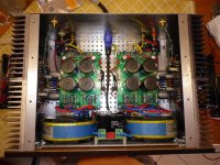
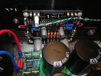
After a long time, I was finally able to complete fabulous FAB USSA-5 amplifier. First of all, many thanks to FAB, not only for this design and boards, but also for excellent QOS and his willingness always answer the questions, even though they could be asked many times by many members before. Many thanks to other members for sharing their knowledge and inspiration as well. Here you can see some photos of my amp.
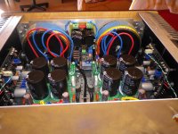
@Amadeus. Gorgeous build! What PSUs are in use there? Very compact.
If I am not mistaken, these PSUwere developed by PROJECT16. You can find his thread here on the forum: CRC Power Supply (Class A amplifier). I am not sure why later PROJECT16 was not organizing group buy for these boards, but PRASI was selling them. At first, I ordered 02 boards from PRASI in 2019. These were well made, however when I started building my amplifier, I wanted black PSU boards in order to match USSA-5 black boards. I contacted PRASI and asked him if black colour is also available, or if he can get them and I would pay him additional cost. In the end PRASI sent me gerber files, so I sent files to manufacturer (seeedstudio) and ordered 05 pieces. I know that there might be some ethical issue ... PROJECT16 is the author, however I made them just for my needs, still got 03 spare, so if somebody is interested, let me know 😊 Second thing is that I should opt for thicker plates, these boards are 1,6mm thick with 2oz copper plating and normal HASL type of finish. Definitely not the quality provided by FAB. Reason why I choose 1,6mm was mainly the price, since I was ordering the smallest possible batch (still quite expensive). Long story short, these are CRC Power Supply (Class A amplifier) developed by PROJECT16
I take this opportunity and would like to ask you if you have any new contact with member Project16...
I have sent him an email without reply, also it has been a long time as a presence in the forum I hope he is well.
Very kind man!!
I have sent him an email without reply, also it has been a long time as a presence in the forum I hope he is well.
Very kind man!!
Last edited:
I take this opportunity and would like to ask you if you have any new contact with member Project16...
I have sent him an email without reply, also it has been a long time as a presence in the forum I hope he is well.
Very kind man!!
Project16 has health problems. He cannot, for the time being, take part in the forum.
I would like to take this opportunity to wish him a good recovery.
We miss him with his extreme kindness.
nounouchet
nounouchet,
Sorry to hear that Project16 is experiencing health issues - wish him recovery soon and good health.
Sorry to hear that Project16 is experiencing health issues - wish him recovery soon and good health.
- Home
- Amplifiers
- Solid State
- USSA-5 Build with Review