Thanks Fab, let me check all the test point voltages and report back tonight. Hopefully its a minor issue and not the hard to find transistors ")
All was working fine till now and without any changes either upstream/downstream any power fluctuations the offset jumped so high.
All was working fine till now and without any changes either upstream/downstream any power fluctuations the offset jumped so high.
Do you know if the UMS heatsinks are one piece per side units and the regular ones that came with the chassis are 2 piece per side? Would the one piece units be an advantage for heat dissipation?
300mm = 1 piece heatsink
400mm = 2 piece heatsink
Hello Fab, here are my test points voltages:
TP9-TP10=27.2mV
TP11-TP12=27.9mV
TP7-TP1=3.88v
TP8-TP3=3.37v
TP5-TP1=1.818v
TP6-TP3=1.164v
TP1-TP2=61.7mV
TP3-TP4=61.6mV
OUT-GND=starts at 11.9/12v and slowly drops and I could see till 7.5v but as M2 was getting hot did not want to go any further.
Appreciate the help as always Fab
TP9-TP10=27.2mV
TP11-TP12=27.9mV
TP7-TP1=3.88v
TP8-TP3=3.37v
TP5-TP1=1.818v
TP6-TP3=1.164v
TP1-TP2=61.7mV
TP3-TP4=61.6mV
OUT-GND=starts at 11.9/12v and slowly drops and I could see till 7.5v but as M2 was getting hot did not want to go any further.
Appreciate the help as always Fab
Last edited:
Hi manniraj
Your measurements are good…..Physics law states that you cannot have dc offset from the amp with a balanced M1 and M2 current in a normal condition.
Have you disconnected your dc protection circuit board from USSA5 board output to ensure the latter is not the problem ?
When M2 starts getting hot until you switch off amp what is the TP4-TP3 measure? And TP6-TP3?
Can you check OUT-GND measure in multimeter AC mode.
Can you report psu voltage for both polarity .
Is your input GND connection firm and secure ?
You can short input terminals for your measurements.
With power off (and after psu caps are discharged) can you measure resistance between PGND-GND on pcb.
Check your fast on terminals to ensure they are nor starting to make a loose connection (it can happen after several connection/disconnection process.
Fab
Last edited:
Have you disconnected your dc protection circuit board from USSA5 board output to ensure the latter is not the problem ? Yes my above measurements is without protection module.
When M2 starts getting hot until you switch off amp what is the TP4-TP3 measure? And TP6-TP3? 61.8mV and 1.138v
Can you check OUT-GND measure in multimeter AC mode. 4.6vac slowly dropping and in 5 mins it became 2.7vac and more or less stabilised
Can you report psu voltage for both polarity . this is correct +/- 27.6vdc and polarity is correct
Is your input GND connection firm and secure ? Yes and now I even changed the psu to another new one with the these measurements
You can short input terminals for your measurements. Yes and I have shorted for the test points and offset measurements now and also the earlier ones too.
With power off (and after psu caps are discharged) can you measure resistance between PGND-GND on pcb. It is like more than 2M as in my DMM with disconnecting the cables from the psu. With the ground cables connected to psu its around 1.7 ohm
Check your fast on terminals to ensure they are nor starting to make a loose connection. I rechecked all and they are nice and tight without any loose connections in spades.
Also I see now that the M1 also gets hot after few mins of M2 getting hot. This seems to be some very weird issue with my amp
Thanks
Last edited:
Hi manniraj
“… With power off (and after psu caps are discharged) can you measure resistance between PGND-GND on pcb. It is like more than 2M as in my DMM it shows as 1 in the 2M position”
Between PGND and GND terminals is R27. Thus your R27 is gone since it should be < 4.7 ohms. Optimal value is 1 ohm. The result is that you have a big part of the circuit floating giving unpredictable results. If you do not have a spare 1W low ohms resistor (1 or 2 ohms) you can put a jumper wire instead to verify it works afterwards. You can even stay like that since it is just a little more sensible to output GND current variations. Not sure it is even audible but it shows on precision instruments.
Fab
Last edited:
Yes manniraj you are spot on. I forgot to tell you to disconnect your psu from USSA-5 board but you did since you are wise. The psu connection is not making the path to input and feedback ground but R27 does.
However, I would expect that PGND-GND has a lower value than 1.6 ohms when connected to PSU which is shorting both terminals.
It may be due to your DMM cables connection too.
Fab
However, I would expect that PGND-GND has a lower value than 1.6 ohms when connected to PSU which is shorting both terminals.
It may be due to your DMM cables connection too.
Fab
Last edited:
This is really good news manniraj. I am glad I could help.
I hope you will continue to listen to music with it for another year ………………..and more!
Fab
Haha hopefully for many more years Fab
But I guess some loose wiring of ground from the PSU to the GND/PGND might have blown the R27 resistor. I did few times removed and connected as I built from single chassis to mono blocs.
Thanks

5B resistors question
Hi Fab. I finally started stuffing my boards this weekend. Just a question regarding resistors RV1A, RV2A, RV1B, and RV2B for the USSA-5B build. These 4 are all replaced with jumpers (0 ohm) for the 5B. At what point do I solder them in? RV1B and RV2B from the start, but RV1A and RV2A only after 8.18 - Driver transistors bias adjustment? Or can I solder all 4 of them from the start?
PS: I saw some exciting news about a new 5.2 version on the test bench.
Hi Twocents
Just install jumpers from the start. RV purpose was to adjust for mosfet big VGS differences between N and P channel. Bjt vbe variations between N an P are small enough so no need to adjust drive current.
Good luck with the rest
Yes version 5.2 is coming along, stay tuned..
In fact it has already passed the bench tests successfully. Now listening tests on-going.
Fab
Last edited:
UMS heatsinks and Toroids.
Hi TMAS.
I tried to use UMS heatsinks in my build, but had to return them. UMS is not compatible with USSA-5 PCB layout. One side of chassis is composed of 02 (sub) heatsinks, since it is 400mm in length as stated by VUNCE. I bought normal 04U 400mm unit and taped holes by myself, BUT I also had to buy benchtop drill (another piece of my economical suicide when building USSA )
The heat dissipation is quite a strange thing for me… I did not measure it by thermometer, but one sub heatsink is always hotter than another one. The component of heatsink where power transistor is attached more to the edge is cooler than sub heatsink where power transistor is close to the centre. It same for both sides of chassis (both channels), and since there is mirroring effect, polarity of transistors have no effect on it. Quite strange for me.
Anyway, there was also some discussion about transformers, If I was building another USSA-5 I would definitely use 400VA transformers instead of 300VA which I have right now. Bigger is always better, and toroids from TOROIDY for values of 300VA and 400VA are identical. Only difference is price (not so big) and weight (no major contribution to overall weight). Anyway, you are not going to move your amp regularly.
Do you know if the UMS heatsinks are one piece per side units and the regular ones that came with the chassis are 2 piece per side? Would the one piece units be an advantage for heat dissipation?
Hi TMAS.
I tried to use UMS heatsinks in my build, but had to return them. UMS is not compatible with USSA-5 PCB layout. One side of chassis is composed of 02 (sub) heatsinks, since it is 400mm in length as stated by VUNCE. I bought normal 04U 400mm unit and taped holes by myself, BUT I also had to buy benchtop drill (another piece of my economical suicide when building USSA
) The heat dissipation is quite a strange thing for me… I did not measure it by thermometer, but one sub heatsink is always hotter than another one. The component of heatsink where power transistor is attached more to the edge is cooler than sub heatsink where power transistor is close to the centre. It same for both sides of chassis (both channels), and since there is mirroring effect, polarity of transistors have no effect on it. Quite strange for me.
Anyway, there was also some discussion about transformers, If I was building another USSA-5 I would definitely use 400VA transformers instead of 300VA which I have right now. Bigger is always better, and toroids from TOROIDY for values of 300VA and 400VA are identical. Only difference is price (not so big) and weight (no major contribution to overall weight). Anyway, you are not going to move your amp regularly.
Last edited:
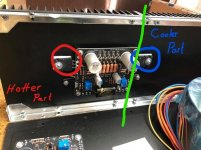

Little visualisation.
I think your temperature difference is just normal since your output transistors are not centered on heatsinks.
I do not use a bench top drill but only a regular drill for the holes. Very rarely I had experienced issues.
300VA transformer for each channel should be more than adequate for this amplifier. Why do you suggest 400 VA?
Fab
Last edited:
- Home
- Amplifiers
- Solid State
- USSA-5 Build with Review