Little change to official Hi-Res Logo.
This is VERY good 😛 even the silver back is there!
 I like it a lot!
But I have changed my avatar recently….😉
Fab
Last edited:
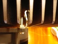
I think your temperature difference is just normal since your output transistors are not centered on heatsinks.
I do not use a bench top drill but only a regular drill for the holes. Very rarely I had experienced issues.
300VA transformer for each channel should be more than adequate for this amplifier. Why do you suggest 400 VA?
Fab
I decided to use bench drill because there is guarantee of having proper vertical alignment of drill with heatsink and also better regulation of setting depth stop while drilling. But I think it all depends how much skill you have, for me bench drill was a way to go.
Speaking about suggesting more power for transformers than recommended, I am not sure if there is some scientifical explanation. More power for the same voltage should equal to thicker copper wiring, which should also have better conductivity and smaller resistance. I was watching some video with CEO of PS AUDIO and they are always using much more powerful transformers than necessary. They do not have scientific explanation, but to them overkilled transformers just sounds better.
Hi Fab. Can C3, C4 be replaced with low ESR electrolytics? I have difficulty sourcing Polymer caps. But I don't want to compromise on SQ.
Hi Twocents
If the 16V version is not available at this moment you can use 6.3V version with no issue.
Fab
If the 16V version is not available at this moment you can use 6.3V version with no issue.
Fab
What is a good length of spacer to be placed between the USSA-5 board and heat sink? I plan on using M3 hardware.
https://www.mouser.com/RAF-Electron...ctfZ1yzvvqx?P=1yzdrreZ1z0izdyZ1y9kp2mZ1yzvkii
https://www.mouser.com/RAF-Electron...ctfZ1yzvvqx?P=1yzdrreZ1z0izdyZ1y9kp2mZ1yzvkii
Hi tmas
I use 5 mm height. This is the minimum height if you use 1 mm thick ceramic plate insulator. Even if you use silicon pad or mica and grease then I would still use 5 mm height for spacer.
Fab
I use 5 mm height. This is the minimum height if you use 1 mm thick ceramic plate insulator. Even if you use silicon pad or mica and grease then I would still use 5 mm height for spacer.
Fab

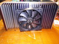
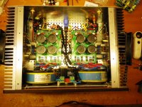
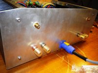
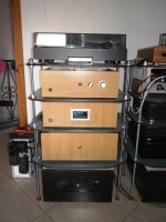
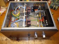
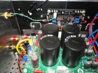
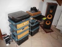
Hello, I made some changes in the bias from 1.3 A to 1.4 A with the help of two 12 cm PWM fans on the outside of the heatsinks. The temperature changes do not affect the stability of the bias or the offset (1-3mv), im playing with no entry Cap . I have set the start to 45C and the stop of them at 43 C . the internal temperature in the box did not exceed 40 C. Ambient temp about 30-31 C. Very very pleasent Amplifirer!!!
Attachments
-
 IMGP0083.jpg833.1 KB · Views: 296
 -
 IMGP0290.jpg997.7 KB · Views: 290
 -
 IMGP0285.jpg1,004.9 KB · Views: 288
 -
 IMGP0076.jpg678.6 KB · Views: 287
 -
 IMGP0297.jpg980.4 KB · Views: 282
 -
 IMGP0298.jpg998.1 KB · Views: 170
 -
 IMGP0270.jpg539.5 KB · Views: 169
 -
 IMGP0275.jpg999.7 KB · Views: 194
 -
 IMGP0294.jpg996.2 KB · Views: 195
 -
 IMGP0269.jpg789.6 KB · Views: 178
Last edited:
Very nice Niko. I run mine at 1.4A and like you, I enjoy this amp.
Are the fans noisy or don't you hear them when music is playing?
Are the fans noisy or don't you hear them when music is playing?
Hi Niko
Yes indeed nice implementation.
You can also try one or more tweaks to your boards:
1) change source resistors value form 0.05 ohms to 0.02 or even 0.01 ohms. You will get even more class A envelope for the same output bias. Ensure to readjust bias accordingly.
2) increase driver current to about 50ma. Reduce driver resistors value keeping the same ratio between positive and negative sections.
3) use a slightly different current for input current sources for positive and negative sections. This will change H2 level without affecting other harmonics. Refer to build manual for USSA5.1 version, section 19.1.3.1 note.
4) reduce slightly both positive and negative input current to increase damping factor.
Fab
Last edited:
Very nice Niko. I run mine at 1.4A and like you, I enjoy this amp.
Are the fans noisy or don't you hear them when music is playing?
Ηi my friend Harry.
the fans is very very quiet(only PWM fans) you can also adjust the rotation force to 10 levels I use this...
DC 5V 12V PWM Speed Controller Fan Speed governor 2 3 4 Wires Computer Temperature control Switch for PC CPU Cooler Fan Alarm|Switches| - AliExpress
Slip Stream 120 PWM - Scythe EU GmbH : Scythe EU GmbH
Νothing is heard you have to approach at a distance of 30cm to hear the rustling of the air not the fans ....
Attachments
Last edited:
Thank my friend Fab!!
Hi Niko
Yes indeed nice implementation.
You can also try one or more tweaks to your boards:
1) change source resistors value form 0.05 ohms to 0.02 or even 0.01 ohms. You will get even more class A envelope for the same output bias. Ensure to readjust bias accordingly. Ok
2) increase driver current to about 50ma. Reduce driver resistors value keeping the same ratio between positive and negative sections.
You mean from 23mA to 50mA ? I must recalculate the resistors?
8.18 Driver transistors bias adjustment
8.18.1 Positive side:
IM3pre = VGSP / 147 Ohm = __________
We need to increase current to about 23mA for IM3, thus:
RM3 = VGSP / 23mA = ________
RV1 = RV1A //RV1B = RM3 -47 = __________
RV1A = _________
Note: In case RV1 is a negative value, R13 must be reduced and above equations must be re-applied accordingly.
8.18.2 Negative side:
IM4pre = VGSN / 94 Ohm = __________
We need to increase current to about 23mA for IM4, thus:
RM4 = VGSN / 23mA = ________
RV2 = RV2A //RV2B = RM4 -47 = __________
RV2A
3) use a slightly different current for input current sources for positive and negative sections. This will change H2 level without affecting other harmonics. Refer to build manual for USSA5.1 version, section 19.1.3.1 note.
Example: 27mV between TP9/TP10 and 29mV between TP11/TP12. ?
4) reduce slightly both positive and negative input current to increase damping factor.
Let say from 28mv to 26 mv?
Fab
Hi Niko
2) yes but you do not need to redo all these calculations since you already have your ratio of equivalent resistor value between positive and negative, you simply divide these values by the ratio of 50ma/25ma. So, 50/25 = 2.
If you have let say R13 + RV1a// Rv1b = 75 ohms then you change it to 36 to 37 ohms or so.
If you have let say R14 + Rv2a // Rv2b = 50 ohms then you change it to 24 or 25 ohms or so.
Notes:
-If you have used 23ma driver current for 1A bias then you should have probably about 25ma or so for 1.4A output bias.
- 50ma is not an absolute value you can have from 45 to 55 ma for about same effect.
3) yes
4) yes. You can go down to even 24 or so for a bigger increase of the DF.
Of course doing one or more of these steps needs dc offset and output bias re-adjustment.
Good luck.
Fab
Last edited:
Hi AnthonyA
I have 3 good news :
1) USSA-5.2 : it has been almost 3 weeks of listening. This version is meeting my expectations. Damping was initially about 70 but I reduced it to be about 50-55 to be similar to my 5.1 version to keep as much as possible the USSA-5 sound signature. This version sounds good but is somewhat a bit different than 5.1. It is quite fast, precise and dynamic sounding. Sound stage is wide and a bit coming more from the back of speakers. Separation of instruments is very pronounced with easy hearing of ending notes. I would say a bit more “analytic “ than version 5.1 because of the sparks but not in a bad way.
2) USSA-5.1 Sanken darlington bjt drivers are back in stock at Digi-Key (maybe the last batch) so hurry up for those still planning to build this USSA-5.1 version.
3) I am testing first channel of the USSA-3.2B version on my bench: jfet input IDSS 8-9 ma, FQP3 type mosfet drivers and MJL bjt as outputs. Damping Factor is about 60 into 8 ohms.
THD is quite low at 1W and only 1A bias :< 0.002% even with intended H2 dominant. H3 is < 0.001%. No higher harmonics visible.
Stay tuned.
Fab
Last edited:
Fab,
Thanks for sharing the subjective and some technical details on USSA-5.2.
Would you mind to do a quick recap on what changes have been made to USSA-5.2 vs original USSA-5? Or if this has been discussed earlier, if you can point me towards that post it would be very helpful. 🙂
Thanks for sharing the subjective and some technical details on USSA-5.2.
Would you mind to do a quick recap on what changes have been made to USSA-5.2 vs original USSA-5? Or if this has been discussed earlier, if you can point me towards that post it would be very helpful. 🙂
Last edited:
Thanks, Fab for your new versions.
I have started to collect parts for the Jfets input design.
Hopefully can build one soon.
I have started to collect parts for the Jfets input design.
Hopefully can build one soon.
Thanks guys for your encouragement.
For more details on version 5.2 refer to these posts:
USSA-5 PCB GB
DF can be increased easily and mosfet driver is readily available.
It also benefits from the tweaks done :
USSA-5 Build with Review
I also have good expectations from version 3.2B which can use easy to obtain mid value [6-10]ma IDSS jfet.
Fab
Last edited:
- Home
- Amplifiers
- Solid State
- USSA-5 Build with Review