Okay, I'll admit I was hasty.
However, show me a case where increasing Cdom improves the distortion of an amplifier.
In every case Cdom increases the distortion waveform that reaches the input stage, usually simply by decreasing the VAS gain. There are edge cases with harmonic cancellation and pathological instability, but those aren't what we are interested in.
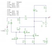
See picture for the 2T VAS.
Hi, Edmond,
Do you have chance to test with R4 removed?
What is the purpose of degeneration the vas.
Okay, I'll admit I was hasty.
However, show me a case where increasing Cdom improves the distortion of an amplifier.
In every case Cdom increases the distortion waveform that reaches the input stage, usually simply by decreasing the VAS gain. There are edge cases with harmonic cancellation and pathological instability, but those aren't what we are interested in.
Actually, regarding Cdom, there should more concern on slew rate, instead of distortion, though lower slew rate may cause larger distortion. IPS sometimes just could not keep up to correct the error.
Okay, I'll admit I was hasty.
However, show me a case where increasing Cdom improves the distortion of an amplifier.
In every case Cdom increases the distortion waveform that reaches the input stage, usually simply by decreasing the VAS gain. There are edge cases with harmonic cancellation and pathological instability, but those aren't what we are interested in.
As long as the amplifier is stable, increasing Cdom will increase distortion, mainly due to increased current requirement from the input stage and decreased feedback loop gain.
Cheers,
Bob
Hi jxdking,Hi, Edmond,
Do you have chance to test with R4 removed?
See picture below.
Current sense resistor, which together with Q1 protect the VAS against excessive currents.What is the purpose of degeneration the vas.
Cheers, E.
Attachments
Current sense resistor, which together with Q1 protect the VAS against excessive currents.
I see. It's not optimal.
You may try to use a current source to load the collector of the Q2.
The current source should be set at above the current of Q2.
I did this in my project. Thus you do not need R4.
I just found out my original design posted in this thread back in 2013!
Bob Cordell's Power amplifier book
Bob Cordell's Power amplifier book
The VAS can be modeled as an inverting amplifier at its simplest Since the output of the VAS is Vdiff.gm/s.C, there must be feedback, and therefore linearization taking place.
There are confounding factors here like the usually non-linear OPS load (increasing load as f increases and as Vo increases over the output voltage swing), so these mechanisms have to be isolated to test the proposition that Cdom does not reduce distortion IMV.
🙂
There are confounding factors here like the usually non-linear OPS load (increasing load as f increases and as Vo increases over the output voltage swing), so these mechanisms have to be isolated to test the proposition that Cdom does not reduce distortion IMV.
🙂
I am talking about the distortion of the amplifier, if you isolate the VAS you are only talking about the distortion of the VAS, not the amplifier.
A highly linear VAS will faithfully convey the distortion of the output stage to the input stage. The goal is to reduce the distortion, not preserve it's integrity.
I already mentioned how Cdom linearizes the VAS, the point is that this linearization is hardly useful to the practical goal of designing a low distortion amplifier. Let's set practical goals.
Last edited:
Well, I am talking about the distortion of the VAS. A good VAS will contribute very little distortion to overall amplifier distortion, the main culprit being the OPS. Nevertheless, reducing its overall contribution and ensuring it is less affected by the OPS load vagaries are worthy objectives. There’s no doubt Cdom plays a role here in achieving that goal.
Hi jxdking,
See picture below.
Current sense resistor, which together with Q1 protect the VAS against excessive currents.
Cheers, E.
Hi Edmond,
While it is certainly true that the VAS emitter resistor is there to sense current and protect the VAS, the main reason I use it is to provide emitter degeneration. Emitter degeneration helps linearize the VAS and greatly increases its output impedance and reduces Early effect in the absence of a cascode. Even with a cascode, I would still degenerate the VAS.
The reduction in effective gm of the VAS transistor by emitter degeneration is of virtually no consequence, since there is more than enough gain to go around in an amplifier with a 2T VAS and a current mirror load for the input stage.
Cheers,
Bob
I use 100R VAS emitter resistor paralleled with RC, where R is less then half VAS emitter resistor and C is in nF values between 100nF to 470nF, in my CFA mosfet amps, and OITPC compensation.🙂
Hi Edmond,
While it is certainly true that the VAS emitter resistor is there to sense current and protect the VAS, the main reason I use it is to provide emitter degeneration. Emitter degeneration helps linearize the VAS and greatly increases its output impedance and reduces Early effect in the absence of a cascode. Even with a cascode, I would still degenerate the VAS.
The reduction in effective gm of the VAS transistor by emitter degeneration is of virtually no consequence, since there is more than enough gain to go around in an amplifier with a 2T VAS and a current mirror load for the input stage.
Cheers,
Bob

I've spent hundreds of hours building and measuring power op-amps for instrumentation. Maximizing Miller-feedback loop-gain has always been consistently instrumental to keeping the overall distortion of an amplifier below my measurement limit for as long as possible as frequency rises.
This means, amongst other things, using as little VAS emitter degeneration as possible. Sometimes a little degeneration is helpful to the goal of frequency compensating the Miller-feedback loop itself (whether it encloses more than just the VAS transistors or not), but as insofar as distortion goes, in most cases, less is ultimately better.
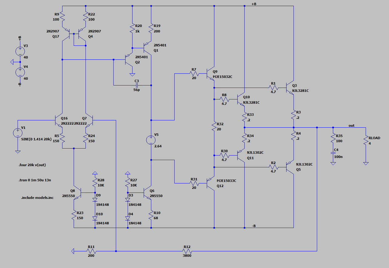
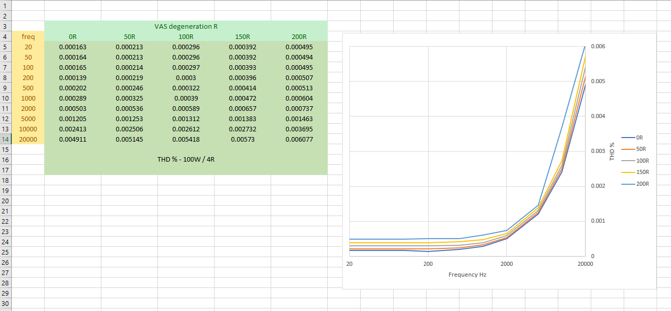
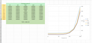
Just for the sake of it, attached is a quick sim of a typical 100W / 4 ohm "Blameless" amplifier with a global ULGF of ~830 kHz. The VAS emitter degeneration was stepped from 0 to 200 R in 50 R increments. For each value of degeneration the THD was taken at 1/2/5 frequency intervals from 20Hz to 20kHz.
The ratio of highest to lowest distortion (over the range of degeneration) is greatest at the lowest audio octaves, which is exactly as one should expect. This is because the most important parameter of the VAS, as far as its ability to drive the non-linear load of the power output stage is concerned, is its ability to keep its output impedance low. At low frequencies feedback via the Miller-feedback compensation capacitor is minimal and you're now relying on on the VAS transconductance being as high as it can be to keep the Miller-feedback loop gain up.
This means, amongst other things, using as little VAS emitter degeneration as possible. Sometimes a little degeneration is helpful to the goal of frequency compensating the Miller-feedback loop itself (whether it encloses more than just the VAS transistors or not), but as insofar as distortion goes, in most cases, less is ultimately better.
Just for the sake of it, attached is a quick sim of a typical 100W / 4 ohm "Blameless" amplifier with a global ULGF of ~830 kHz. The VAS emitter degeneration was stepped from 0 to 200 R in 50 R increments. For each value of degeneration the THD was taken at 1/2/5 frequency intervals from 20Hz to 20kHz.
The ratio of highest to lowest distortion (over the range of degeneration) is greatest at the lowest audio octaves, which is exactly as one should expect. This is because the most important parameter of the VAS, as far as its ability to drive the non-linear load of the power output stage is concerned, is its ability to keep its output impedance low. At low frequencies feedback via the Miller-feedback compensation capacitor is minimal and you're now relying on on the VAS transconductance being as high as it can be to keep the Miller-feedback loop gain up.
Attachments
Last edited:
Another thing that might be worth mentioning is that degenerating the VAS in not at all analogous to degenerating the input stage as far as the transconductance/linearity trade off is concerned. Unlike when degenerating the VAS, there is no such tradeoff at all when degenerating the input stage (IPS).
To a first order analysis the amplifiers ULGF is determined by three variables - the IPS transconductance, the value of the Miller-feedback compensation capacitor and the the value of closed loop gain.
With the closed loop gain and the value of the Miller compensation capacitor set, in order to set your desired ULGF, you've got a specific value of IPS transconductance to design for.
You can either run the IPS un-degenerated and simply program the target transconductance with the tail current, or you can set the tail current much higher (say x10) than required to achieve the required transconductance in the un-degenerated case, but then degenerate back down to the required value.
Both methods end up with the same result as far as transconductance goes, buy the latter method results in an IPS with much better linearity. The take away here is that you've dramatically improved the linearity of the IPS, but in doing so you have not in any way thrown away a big chunk of beneficial loop gain.
In comparison to the IPS, the VAS with, say, a typical Iq of 10mA or so, is already running "hot" and there really isn't any practical/worthwhile scope for making up for the transconductance lost to degeneration by running it any hotter.
Last edited:
Try the same experiment with an output triple EF. Double EFs are inferior, especially when driving a 4-ohm load. That just clouds the picture.
Cheers,
Bob
Cheers,
Bob
That just clouds the picture.
How so? By demonstrating that some of the truths expounded here about the interplay of VAS parameters to amplifier distortion aren't, as a matter of fact, universally true?
Like it or not, in the world of discrete audio power amplifiers the double EF, despite its limitations, is probably the most ubiquitous bipolar power output stage out there.
I've spent hundreds of hours building and measuring power op-amps for instrumentation. Maximizing Miller-feedback loop-gain has always been consistently instrumental to keeping the overall distortion of an amplifier below my measurement limit for as long as possible as frequency rises.
This means, amongst other things, using as little VAS emitter degeneration as possible. Sometimes a little degeneration is helpful to the goal of frequency compensating the Miller-feedback loop itself (whether it encloses more than just the VAS transistors or not), but as insofar as distortion goes, in most cases, less is ultimately better.
Just for the sake of it, attached is a quick sim of a typical 100W / 4 ohm "Blameless" amplifier with a global ULGF of ~830 kHz. The VAS emitter degeneration was stepped from 0 to 200 R in 50 R increments. For each value of degeneration the THD was taken at 1/2/5 frequency intervals from 20Hz to 20kHz.
The ratio of highest to lowest distortion (over the range of degeneration) is greatest at the lowest audio octaves, which is exactly as one should expect. This is because the most important parameter of the VAS, as far as its ability to drive the non-linear load of the power output stage is concerned, is its ability to keep its output impedance low. At low frequencies feedback via the Miller-feedback compensation capacitor is minimal and you're now relying on on the VAS transconductance being as high as it can be to keep the Miller-feedback loop gain up.
You have done a very good job refuting the very false assertion made by some that resistively degenerating the second stage improves linearity. Excellent work! Well done!
Last edited:
Like it or not, in the world of discrete audio power amplifiers the double EF, despite its limitations, is probably the most ubiquitous bipolar power output stage out there.
Notwithstanding its popularity, the double emitter-follower output stage is significantly inferior to the Locanthi-type triple emitter-follower output stage in virtually all respects.
To degenerate or not to degenerate.
How on earth could I forget this important aspect of the VAS emitter resistor? Probably because I was too much focused on the result of my latest sim, which showed hardly any effect of the degeneration resistor on distortion figures.
Anyhow, I agree with you that this resistor does play an important role in minimizing the Early effect and increasing the output impedance.
Whether this also helps to reduce distortion is another story. It depends on the circuit details (as usual).
As poldaaudio has shown, it's even better to use no degeneration resistor at all as far as a "blameless" amplifier is concerned.
In case of my Super TIS however, it's vital to keep the Early effect as low as possible and and keep the output impedance as high as possible, otherwise the low distortion figures were not possible.
Cheers, E.
Hi Bob,Hi Edmond,
While it is certainly true that the VAS emitter resistor is there to sense current and protect the VAS, the main reason I use it is to provide emitter degeneration. Emitter degeneration helps linearize the VAS and greatly increases its output impedance and reduces Early effect in the absence of a cascode. Even with a cascode, I would still degenerate the VAS.
The reduction in effective gm of the VAS transistor by emitter degeneration is of virtually no consequence, since there is more than enough gain to go around in an amplifier with a 2T VAS and a current mirror load for the input stage.
Cheers,
Bob
How on earth could I forget this important aspect of the VAS emitter resistor? Probably because I was too much focused on the result of my latest sim, which showed hardly any effect of the degeneration resistor on distortion figures.
Anyhow, I agree with you that this resistor does play an important role in minimizing the Early effect and increasing the output impedance.
Whether this also helps to reduce distortion is another story. It depends on the circuit details (as usual).
As poldaaudio has shown, it's even better to use no degeneration resistor at all as far as a "blameless" amplifier is concerned.
In case of my Super TIS however, it's vital to keep the Early effect as low as possible and and keep the output impedance as high as possible, otherwise the low distortion figures were not possible.
Cheers, E.
Last edited:
- Home
- Amplifiers
- Solid State
- Bob Cordell's Power amplifier book