The leakage inductance acts as an impedance between two voltage sources namely, the filter capacitor and the mains voltage. It limits the dI/dt in the circuit (inrush etc.) and also provides some parasitic filtering of the output DC. Also, the leakage is always there and methods that reduce it usually end up increasing the interwinding capacitances. Opinions vary.
However, leakage is a disadvantage in a HF (SMPS) transformer, as the energy stored in the leakage would cause severe ringing, especially when the converter is heavily loaded (E ∝ I^2).
However, leakage is a disadvantage in a HF (SMPS) transformer, as the energy stored in the leakage would cause severe ringing, especially when the converter is heavily loaded (E ∝ I^2).
Leakage inductance can benefit high power industrial commutation due to the significant level of reverse recovery or turn-off time given the devices and very high currents. But this application does not impose those disadvantages, and modern semiconductors can be used to manage commutation transients, rather than chunky vintage glitches.
Last edited:
Well, then what would you recommend? Sandwiched pri/sec (min. leakage)?
Even I happened to think of "amps" being amplifiers first.
trobbins said:Are you sure you want up to 25 amplifiers to use a single common +/- power supply ..
Even I happened to think of "amps" being amplifiers first.
Last edited:
The 1W you specify is the speaker power (not that of the amplifier)
The 1 W specified does seem to be the amplifier power, he mentions a 4 W per channel amplifier and then says he doesn't use more than 1 W.
Your 1 W "speaker" power, or 1 W acoustic is far more reasonable, but I think your reasonableness has lead you to misinterpret an unreasonable post.
but what if the OP has a stack of class A amplifiers?
Class B+ at the moment but the plan is to replace them with more efficient Class H units with modulated rails.
...the connector...is the least of the OP's worries!
Especially now I have learned of the Han series connectors and seen the Powersoft.
Are you 3-way all around (21ch + 2 BTL subs)?
My fault that I didn't write clearly, I did mean 25 amp(ere)s as you worked out in your next post.
But I would like to bi-amp eventually, which will require quite a lot of amplifiers, so the 25 amplifier interpretation is not far off.
That's why I didn't comment about "trobbins" similar misinterpretation.
In case you find it hard to calculate what you need, you could always work back to the power supply from the speaker, that is:
85dBSPL (105dBSPL peak) in your seat (cinema standard) => speaker power => amplifier power => mains power
Yes, I have already done this, but I wanted Jean-Paul to provide his numbers first because I felt that whatever numbers I used he would quibble.😉
In the bass channel the Dolby standard is actually 115 dB.
I sit a little more than 3 m from the speakers so free field sensitivity will be down 10 dB from 1 m numbers but there's some room boost.
So a better than typical 90 dB @ 1 m @ 1 W becomes about 85 db @ 3 m in the room.
So 115 dB is 1000 W short term.
105 dB for the mains obviously drops it to 100 W.
I have efficient horn loaded mids which drops it even more in the mid-band but power is needed to equalize the mass roll-off in the upper bands so still about 100 W / channel.
Total is in the order of 1000 W + 7 x 100 W = 1700 W
Maybe later add Dolby Atmos vertical channels so ~1800 W.
I want to keep it below 2300 W in case I ever do move house.
Then I would only have to redo the central supply, could run 10 A from a standard power point.
400V line is same as 230V phase.. 240V phase equates to 415V line. ... There's some confusion here.
I plan to connect the transformer primaries in "Y" so that each sees 230/240 V rather than "delta" where they see 400/415 V.
Well, there's no need to hurry, take your time. BTW, is it possible to re-purpose the HF transformer within your blown grid-tied inverter by any chance?
Unfortunately my blown inverter has no transformer, it has been eliminated in the interest of efficiency.
The solar panels arrays are connected to a Maximum Power Point Tracker that uses a boost converter to output about 600 V.
Then the inverter runs directly off that.
There is a lot of extra safety circuitry for protection because of the lack of isolation.
Why not just use two simple 3ph ...100VDC supplies connected in series for the +/-100V common supply?
I have already mentioned that this is an option.
...Or a complementary pair of transformers with delta and wye secondaries...so that the mains enjoys 12 pulse lower harmonics.
And that this is another option.
I can't see any benefit (and only a lot of complexity or cost) [to] then add...some variation of smps' to then
I never proposed this, it has no benefit.
Just visit your local transformer manufacturer...
Custom made transformers in Australia are not cheap.
And the ripple will be worse than a SMPS solution.
But it is my baseline option to which the SMPS options are compared.
If the SMPS looks better than that's what I will pick, otherwise it's transformers, either 6 or 12 pulse.
Very sensible advice above, I must say. It's easier to do...
Thanks for the schematic, I need spit rails so that doubles it all up but that's about what I had in mind, except for "Y" connected primaries.
And the fact it powers amplifiers rather than a motor inverter, of course😉
Best wishes
David
Last edited:
Why would you do that (unless you wanted to use three 240V single-phase transformers and needed the neutral connection) ?I plan to connect the transformer primaries in "Y" so that each sees 230/240 V rather than "delta" where they see 400/415 V.
Maybe I didn't appreciate the meaning of post #51: "A simple 3 phase rectifier followed by a one phase SM transformer would be fine, if I can find one commercially."I never proposed this, it has no benefit.
Without a quote for a transformer for a 2x100Vx100A= 20kW DC loaded power supply, it is difficult to compare pricing with commercial product.Custom made transformers in Australia are not cheap.
And the ripple will be worse than a SMPS solution.
But it is my baseline option to which the SMPS options are compared.
If you are worried about pennies, then maybe the cheapest path forward is to buy a few cheap 300-600W stereo classic PA solid state PA amps with their large +/- 85-105Vdc supplies made with large toroids and filter caps. Just don't use the two amp sections. They often sell for well under $100 in Oz because no one wants them, and people can't sell them if they need repair (which is usually the output devices - so the power supplies are fine). Then you can incrementally add more when needed, or buy 3 PA amplifiers at a time and spread them over the 3 phases.
Last edited:
Why would you do that (unless you wanted to use three 240V single-phase transformers and needed the neutral connection) ?
As you say, so I can then use 240 V transformers.
These are readily available and probably cheaper than a dedicated 3 phase unit.
It also provides me with the possibility to reuse them if I ever do move to a house without 3 phase.
Maybe I didn't appreciate... "A simple 3 phase rectifier followed by a one phase SM transformer would be fine, if I can find one commercially."
Or perhaps I misunderstood your post #58.
I took it that you considered there was no point to follow a 3 phase step down and isolation transformer with a SMPS back end.
Do I understand correctly?
If you are worried about pennies
Not sure if that is attempt to score a cheap point or just an idiom.
I am not worried about pennies, the power supply will be in the order of a thousand dollars, I expect.
The JBL theatre speakers are substantially more expensive than that.
But I do not see any point to make it any more expensive for no reason.
So your idea to use second hand amplifiers is quite sensible.
Best wishes
David
Last edited:
I need spit rails so that doubles it all up..
Not quite, you could make the common point between the rectifiers your power ground, as already mentioned by trobbins in the very next post. Also please note that the said harmonic cancellation results in lower THD, but not necessarily unity pf (uncontrolled rectifier). Please find a small simulation of the circuit (attached), that also uses a grounded star connection for the primary winding.
Dave Zan said:I plan to connect the transformer primaries in "Y" so that each sees 230/240 V rather than "delta" where they see 400/415 V.
That's fine with transformers, but the 560V warning was for the 3-phase SMPS idea (rectifier + HF tfr), as the bridges operate from across phases (i.e. from 400V), with the neutral point not being used at all. Above 600V, the design philosophies change somewhat and it becomes harder to comply with safety, EMC, efficiency, cost and reliability (at the same time) especially from home, wherein the testing/measurement/troubleshooting capabilities of the designer are often limited.
Dave Zan said:Custom made transformers in Australia are not cheap. And the ripple will be worse than a SMPS solution.
You could try "educational 3-phase transformers" often used in colleges, usually rated below 2kVA. A 3-phase bank (3x1ph) transformer is always going to be more expensive when compared to standard 3-phase at the same power. Though there is a path for zero-sequence flux (centre limb) in the bank type, the industry prefers banks mostly for the ease of transportation/installation (3 tfrs, 3 lorries).
The ripple from direct 50Hz operation could be eliminated if you choose to perform either PFC or post regulation (non-isolated synchronous buck maybe), the former being more complicated, obviously.
Alternatively, you could try acquiring the front-end of a 2-3kW air-conditioner that has a built-in single-phase PFC (often SEPIC). Its output (~325VDC) could then be used to drive a regular SMPS, giving the desired output with reduced (HF) ripple, from regular 230V supply.
Dave Zan said:I would like to bi-amp ..... Maybe later add Dolby Atmos vertical channels.....JBL theatre speakers ...
Since, pro JBLs are at least 6dB more sensitive when compared to the HiFi categories, the bi-amped power should not substantially higher, as the HF portions with compression drivers usually end up needing only around 1/10th as much power (vs the LF).
If I remember correctly, the net power from all the off-screen channels are always scaled to add up to that of a front screen channel, and it's very likely that the same is true for the Atmos as well, but not sure, so please check.
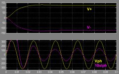
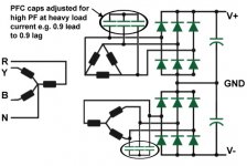
Last edited:
Not quite, you could make the common point between the rectifiers your power ground
I always expected parallel 12 pulse, just from habit, so I haven't analysed the series connection but your common point earth eliminates the 12 pulse rectification surely?
Now we have 6 pulse on plus and minus rails but out of phase.
Other stuff I will think about, just wanted to reply before dinner time!
Best wishes
David
12 pulse for mains. Need an interphase for 12 pulse on output. It gets complex, and comes back to whether you have a need, or a whim.
trobbins said:12 pulse for mains.
Exactly, the 12-pulse thing happens within the core (flux) of the transformer, and thus a happier power-grid company, that's all. You would need an active PFC for a win-win on both sides.
Yes, but that's enough suppression for the amplifier PSRR to take over. Besides, if you're planning to depend on pulse number to clean up the DC, then you would need a lot of pulses to reach satisfaction, as already pointed out by jjasniew in post #3:Dave Zan said:Now we have 6 pulse on plus and minus rails but out of phase.
The only way to get rid of ripple, without capacitive storage, would be to have the number of phases go to infinity....Perhaps look into "power factor corrected" power supply designs...
Last edited:
12 pulse type benefits for the mains are typically related to industrial type applications where loads are mainly resistive, or inductive - the default capacitor input type filter as would likely be used here would still be ugly for the mains.
12 pulse type benefits for the load side are typically for ripple reduction related to large battery charging or electrochemical processes that benefit from low ripple - but both those applications typically use choke input filtering to minimise the large ripple current rating of filter caps that may still need to be added.
I'd suggest that for 12-pulse, the mains side quality is not a concern to the OP, and achieving it on the dc side is too complicated.
Last edited:
Here, in my country, only industries have pf regulations and are supplied from separate 3.3kV lines, that are not used for other purposes. However, I am not very aware of the regulations in Australia, but you (trobbins) obviously know better, since you're from around there, and so is the OP.
Nevertheless, the OP plans to run 25 (more or less) amplifiers from the same DC supply, and therefore I am of the opinion that it may be a good idea to include voltage regulation after the rectifier. That would greatly reduce the supply variations due to the fluctuating audio power, in addition to the suppression provided by the amplifiers' PSRRs. Further, the benefit of such regulation fully goes to the OP and not the power company. 🙂
That's exactly where the transformer leakage is our friend, giving essentially "free" 3-phase chokes on the AC side. Hope you understood the reason behind my split bobbin philosophy from post #59.
Nevertheless, the OP plans to run 25 (more or less) amplifiers from the same DC supply, and therefore I am of the opinion that it may be a good idea to include voltage regulation after the rectifier. That would greatly reduce the supply variations due to the fluctuating audio power, in addition to the suppression provided by the amplifiers' PSRRs. Further, the benefit of such regulation fully goes to the OP and not the power company. 🙂
trobbins said:12 pulse type benefits for the load side are typically for ripple reduction related to large battery charging or electrochemical processes that benefit from low ripple - but both those applications typically use choke input filtering to minimise the large ripple current rating of filter caps that may still need to be added.
That's exactly where the transformer leakage is our friend, giving essentially "free" 3-phase chokes on the AC side. Hope you understood the reason behind my split bobbin philosophy from post #59.
Last edited:
It is connector from company Phoenix Contact:Thanks, brilliant -a heavy duty audio system powered by a 3 phase supply with a removable connector, just what I had in mind.
The connector looks perfect, do you know what it is or if it's readily available?
https://www.phoenixcontact.com/online/portal/au
Also known as Euroblock connector.
Euroblock - Wikipedia
It is connector from company Phoenix Contact:
https://www.phoenixcontact.com/online/portal/au
Also known as Euroblock connector.
Euroblock - Wikipedia
Thank you.
I have only seen Phoenix connectors used with Extra Low V so I expected the mains connector could not be that, must be some other unfamiliar variety - I should have looked up the user manual.
Is there any risk of mix up, I wonder?
Much cheaper than the Han connector, I expect.
Best wishes
Last edited:
12 pulse for mains...
Ok, I meant 12 pulse to reduce ripple on my side.
I am, as you surmised, not so concerned about benefits to the electrical supply company, they can look after themselves.
....for the amplifier PSRR to take over.
I do rely on the amplifier PSRR but it doesn't really help with common mode noise on the rails.
I would like to reduce the ripple on each rail independently, which your connection does not do.
..12-pulse, the mains side quality is not a concern to the OP...on the dc side is too complicated.
For sure on the mains side.😉
On the DC side it's not so much added complication but even so, still not clear whether it's worth it.
Best wishes
David
@Trobbins, you may have missed my question in post #66
I took it that you considered there was no point to follow a 3 phase step down and isolation transformer with a SMPS back end.
Do I understand correctly?
Last edited:
My view was that having some form of mains frequency transformer/rectifier/filter equipment, and then adding a smps block of equipment, had any practical benefit.
3ph input smps 'rectifiers' are commercial and of the power capability that you appear to be after, and are likely able to provide a quality circa 100Vdc output (and hopefully with a floating output that can then allow two such PSU's to operate as a +/- output PSU).
I don't know of any commercial dc-dc smps product that would interface a mains frequency transformer/rectifier/filtered input (of whatever DCV level), to a circa +/-100Vdc output at the power level for your application. As such, I don't see any benefit in that approach, especially if your thought was to diy such a smps from scratch.
I am, as you surmised, not so concerned about benefits to the electrical supply company.
That obviously makes things a lot easier, as you could now place all your focus on the DC/output side of the power supply.
Dave Zan said:..it doesn't really help with common mode noise on the rails.
The CM voltage on the rails depends on the value of the filter capacitor. Attached is a closer shot of the rails from the earlier simulation (V- inverted) that clearly shows a CM voltage less than 1Vpp.
Besides, what do think about a pair of simple, decent performance post-regulators for all the 25 amplifiers together? With no input pf regulations to worry about, they could give you all what you want. Further, you could even build them yourself !
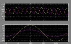
Dave Zan said:...they can look after themselves...
If you don't really care about input pf, you could use a 3-phase transformer in "neither delta nor star configuration" i.e. a transformer with open-end output, followed by single-phase rectifiers in each phase whose outputs are then tied together for ripple reduction (see circuit and simulation attached). For a dual supply, you could simply use a transformer with centre-tapped secondaries, whose centre-tap (also tied) would then be your power ground.
However, I suggest that the neutral connection (star point) be left open on the primary side so as to reject the triplen harmonics drawn by the rectifier circuits. Though that would be doing the power company a favour, it's not going to cost you anything (apart from one less cable).
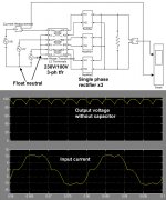
Last edited:
The advantage of the method is that it does not reach 560V like the 3-phase (6 diode) rectifier even with a 1:1 transformer, due to single-phase operation. However, this is at the expense of the input current THD (bottom waveform) and power factor. Sorry, couldn't edit the previous post.
Last edited:
I don't plan a very complex 3 phase SMPS....
A simple 3 phase rectifier followed by a one phase SM transformer would be fine... if I can find one commercially....
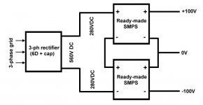
If you're very particular about SMPS, here's is a method that could provide you with a simple, 3-phase, isolated and regulated dual power supply that maybe obtained using commercially available SMPSes (picture), without having to endure the difficulties pertaining to design, testing or prototyping.
- Home
- Amplifiers
- Power Supplies
- 3 phase power supply for audio !