For that sim I looked at the DC voltages at the important points. You can do that either from the transient sim by hovering over the points or you can change the sim to show only a DC analysis.
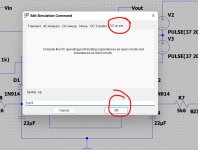
To do that change the sim to run a 'dc op pnt'. When you click OK be sure to drop the new command onto the sim.
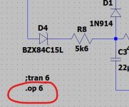
Notice the new command starts with . and the other has changed to ;
The . is the active one.
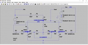
Run the sim and now you can click and attach voltages to nodes.
You can either calculate the resistor value needed using ohms law or cheat and try a few values on the sim 😀 You have to change both resistors at once as they interact.
Was that what you meant or not?
To do that change the sim to run a 'dc op pnt'. When you click OK be sure to drop the new command onto the sim.
Notice the new command starts with . and the other has changed to ;
The . is the active one.
Run the sim and now you can click and attach voltages to nodes.
You can either calculate the resistor value needed using ohms law or cheat and try a few values on the sim 😀 You have to change both resistors at once as they interact.
Was that what you meant or not?
Attachments
I made it up as I only had the circuit diagram you posted way back at the start as a reference. I figured it would be a typical type of supply voltage for that amp.
so you were not far out the actual voltage is 39v, but the other side is 24v so a 15v drop on both zeners so i would say we are ok there.
but the other channel is still a bit weird.I lowered the value on RX1(idle) to 36ohm from 44ohm as it was sitting at 0mv and it only increased the voltage buy 3mv, so thats not right, it should have increased it considerably, i expected it to be way over if anything.
The other weird thing is that the centre voltages are both close to 0v now(i took the soft clip switch out and replaced it after cleaning it up.(I cant see that the switch had an issue as it was only a little dirty)
But on the iffy channel when you switch over from on to off the voltage goes up to 144mv, then slowly over about a minuite returns to 0v,but then wanders between -5mv to +4mv where as the good channel doesnt alter at all as you switch it over.
could we be looking at a cap issue?
there are a few(only the electrlitics for now as the ceramics and foils rearly fail) but i have all of them so im going to try that as im running out of ideas TBH
Last edited:
Lets just be clear on what you are measuring. Is RX1 the resistor on the vbe multiplier, that is the one next to the 180 ohm on your posted diagram.
That is the one that adjusts the bias current.
It is worth checking that both channels have similar voltages across R488 (100 ohm) and that the voltages across R456 and R458 are equal.
The bias current is measured from the volt drop across R462 (1ohm) which you have to have in circuit.
The bias current adjustment should not affect the centre voltage.
I wouldn't automatically condemn any caps for the midpoint voltage fluctuations. The circuit runs on a knife edge for DC balance is extremally critical of (or rather relies on) the thermal characteristics of the appropriate parts of the design all cancelling each other out as the circuit stabilizes. So D404, D02 and those input transistors all rely on this close thermal coupling. If you heat or cool one and not the others then the midpoint voltage will alter significantly.
You could at the voltage across R436 for both channels and see how closely they track. Not absolute values, just whether if one is higher when cold then is the other also similarly higher when cold.
Attachments

so both are 100ohm
voltages across as follws
RX 1 i replaced with a 1K pot to adust the idle, that was adjusted to 26mv
voltage across RX1 solder shorts replaced 593mv
RX1 is 28mv
voltage across RX2 solder shorts replaced 613mv
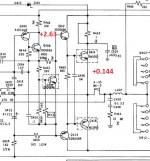
only real difference is, if it matters is the collector voltages- on Q409 its 2.63V and on Q410 its 1.13v
also the base voltages on both of these are only 560mv
R436 471mv R435 465mv
voltages across as follws
RX 1 i replaced with a 1K pot to adust the idle, that was adjusted to 26mv
voltage across RX1 solder shorts replaced 593mv
RX1 is 28mv
voltage across RX2 solder shorts replaced 613mv
only real difference is, if it matters is the collector voltages- on Q409 its 2.63V and on Q410 its 1.13v
also the base voltages on both of these are only 560mv
R436 471mv R435 465mv
Last edited:
only real difference is, if it matters is the collector voltages- on Q409 its 2.63V and on Q410 its 1.13v
also the base voltages on both of these are only 560mv
Edit... is Q409 the vbe multiplier ??? I only have the bit of the circuit you posted with the even numbered channel part.
Lets just look at that.
The voltages themselves tell us little because you are measuring from ground (I assume) but used with the figures of +144mv for the midpoint that you mentioned earlier it might tell us something.
If the midpoint is at approx zero volts then your measured 1.13 sounds about right. It is zero (the midpoint) plus two base/emitter volt drops (the output and driver).
2.63 relative to +144 millivolts tells us that if the readings are accurate then there has to be a problem with either the driver or the output, or some broken print etc. The driver would be favourite.
Can you measure the voltage actually across B and E of that driver but be careful, no probe slips.
multipiers
Q409 b/e 593mv
Q410 b/e 613mv
yes all references to ground
both midpoints are zero but
from turn on cold channel a straight to zero and stays there as it should without fluctuation regardless
from cold channel b starts off 144+mv then drops to around zero within about 15 seconds now, but i did change some of the caps around the clip circuit, but still fluctuates +/- 5mv
when you switch the clip on or off it goes back to the +144mv then drops back down again.
i have done quite a few very 'close up' magnified visual sweeps and couldnt see anything obvious but ill have another look just in case.
its something simple,i have been convinced since the start.Everything i do im learning so i dont have a problem with the time thing, you would have sorted it out ages ago im sure, and i will do to, for sure because i never give up 🙂
Edit... is Q409 the vbe multiplier ??? I only have the bit of the circuit you posted with the even numbered channel part.
Lets just look at that.
The voltages themselves tell us little because you are measuring from ground (I assume) but used with the figures of +144mv for the midpoint that you mentioned earlier it might tell us something.
If the midpoint is at approx zero volts then your measured 1.13 sounds about right. It is zero (the midpoint) plus two base/emitter volt drops (the output and driver).
2.63 relative to +144 millivolts tells us that if the readings are accurate then there has to be a problem with either the driver or the output, or some broken print etc. The driver would be favourite.
Can you measure the voltage actually across B and E of that driver but be careful, no probe slips.
so subsequent to my post after this one, ive changed those multipliers and no difference.the track was crappy though so ive sorted that, but i tested the old ones and they seemed fine
The multiplier will be fine, its the most likely the driver.
This is how it reads. You have a midpoint of +144mv and 2.63 volts on the collector of the multiplier.
So how is the that voltage distributed. You have 2.63 less 0.144 which is 2.49 volts. The two B-E junctions (which are effectively in series) can not support that... something is open circuit or faulty.
Attachments
one thing that happened earlier,i thought i would just test a few diodes, out of desperation realy, not sure why, but i tested the 2 zeners and one had a continuous tone(along with a voltage of 7.65v) nothing in reverse, power off, unplugged.
The other tested same voltage but no tone
so i took it out and replaced it-i then tested it out of circuit and it was like a dead short,failed.
when i turned it back on with the new one in and(with the bulb tester) it lit up quite bright, but just for a short period.
when i tested the diodes with the power back on, they we giving 39v/22v to tested each side to ground, so about 17v drop
does this sound right?
Zeners can not always be reliably checked on a meter. They also have quite a wide voltage tolerance. As long as they drop the correct voltage then all is OK with them.
On your NAD C414 is the only means the soft clip has of altering anything. A fault in the soft clip that either reverse biases the cap or that exceeds its working voltage are the only two conditions that could cause a problem. If you are not sure then just take the cap out while you work on it all.
On your NAD C414 is the only means the soft clip has of altering anything. A fault in the soft clip that either reverse biases the cap or that exceeds its working voltage are the only two conditions that could cause a problem. If you are not sure then just take the cap out while you work on it all.
OK, so that can not effect things as long as it is not reverse biased or has overvoltage across it.
Go back to the driver voltage and see why you have around 2.5 volts across those two junctions. Either the measurement is in error or there is a problem there 🙂
Go back to the driver voltage and see why you have around 2.5 volts across those two junctions. Either the measurement is in error or there is a problem there 🙂
ok ill check tomorrow.im beat.and i think when you are like me,currently with only partial knowledge you proberbly go round in circles, but ill get there 😉
The multiplier will be fine, its the most likely the driver.
This is how it reads. You have a midpoint of +144mv and 2.63 volts on the collector of the multiplier.
So how is the that voltage distributed. You have 2.63 less 0.144 which is 2.49 volts. The two B-E junctions (which are effectively in series) can not support that... something is open circuit or faulty.
the onlt thing i would say with this is its only +144mv for about 10 seconds, then it goes to 0mv
You are doing well 🙂 and you can't hope to pick it all up in one go. Its been a lifelong interest and career for me.
the 144mv and zero volts doesn't matter as long as you are still seeing that high voltage on the collector of the multiplier. That shows a problem.
You should see no more than around 1.2 volts there always assuming the output is close to zero volts.
The more reliable way to measure is using the method of measuring back (or is it forward) from the output line to the multiplier. You should see about 0.6v on the base of the output and then another 0.6 added on the driver base. So 1.2 volts in total.
And I'm done as well
- Home
- Amplifiers
- Solid State
- nad 3130 Centre voltage adjustment issue