Thanks for the quick reply avdesignguru,
I had thought of that also, but I'm worried that space might be a bit tight for leads between the PCB and pot due to the relatively low height of the case I intend to use. I think it's going to be quite a tight fit!
I may end up doing just this, but if anyone can provide the measurement available I'd still appreciate it.
Cheers
Since I have a ruler and my WHAMMY board sitting right next to me I can tell you the measurement is exactly 33mm...Hi all,
Does anyone have the latest version of the unpopulated WHAMMY PCB from diyaudiostore.com and a pair of vernier calipers sitting in front of them? I'm looking for a specific dimensions for the design of a custom front face.
I'm still waiting for my PCBs to arrive (long postal transit times are one of the downsides of living in New Zealand), but need to get cracking on the custom front faces if I'm to get the completed item to my brother in Singapore in time for his birthday at the end of August.
To that end, I'm looking for a specific dimension (preferably in millimetres please!)from the side of the PCB (as you look at it from the top) to the centre line of through holes on P1 (the attenuator). I've included a photo to explain it better than my words can.
Once I have this dimension I'll be able to dimension the front face cutout for the attenuator.
Thanks in advance 🙂
Hi all,
Does anyone have the latest version of the unpopulated WHAMMY PCB from diyaudiostore.com and a pair of vernier calipers sitting in front of them? I'm looking for a specific dimensions for the design of a custom front face.
I'm still waiting for my PCBs to arrive (long postal transit times are one of the downsides of living in New Zealand), but need to get cracking on the custom front faces if I'm to get the completed item to my brother in Singapore in time for his birthday at the end of August.
To that end, I'm looking for a specific dimension (preferably in millimetres please!)from the side of the PCB (as you look at it from the top) to the centre line of through holes on P1 (the attenuator). I've included a photo to explain it better than my words can.
Once I have this dimension I'll be able to dimension the front face cutout for the attenuator.
Thanks in advance 🙂
Where in NZ are you? 🙂
Edit: Oh I just saw there's a few of us in NZ. I was going to say I have a couple of spare boards here you can measure...
Another option is to rotate the pot by 90 degrees and have the pins pointing sideways and the wires looping back under the pot.
Last edited:
Since I have a ruler and my WHAMMY board sitting right next to me I can tell you the measurement is exactly 33mm...
Thanks mate, I owe you a chocolate fish
Where in NZ are you? 🙂
[SNIP]
Another option is to rotate the pot by 90 degrees and have the pins pointing sideways and the wires looping back under the pot.
I'm in Wellington. Thanks for the 90° tip, I hadn't even thought of that. Avdesignguru's comment makes more sense now too!
I am going on memory here, but some member here reported that C2 and C7 fixed some hiss in his headphones and Wayne replied “yes, you did the right thing, that is what they are for”. But I have to emphasize I am going on memory, you may want to search the thread for the exact discussion.
I'm a bit troubled : )
So according to Wayne's keynote at burningamp, those caps cause a small dip in the bass.
I love the rumble on planars at the moment..
That's why I brought up the hiss going away for the few moments when you turn off the power but the music still playing due to caps retaining charge.
Was wondering if something could be done there.
Next option would be getting an impedance adapter.
Also, I strongly recommend not mounting pot on PCB directly.
You will fiddle with the pot several times, it's better if the PCB doesn't directly take stresses from this.
Also, I strongly recommend not mounting pot on PCB directly.
You will fiddle with the pot several times, it's better if the PCB doesn't directly take stresses from this.
Well, that seems like a strong consensus to me - I won't hard-mount the pot to the PCB!
Thanks MadHatterRyu
Well, I have the pot off the PCB as well, but if you secure the pot with the smaller 'pin' next to the main shaft and also with the nut, there shouldn't be any stress on the PCB....Also, I strongly recommend not mounting pot on PCB directly.
You will fiddle with the pot several times, it's better if the PCB doesn't directly take stresses from this.
If you leave it 'floating' in the front panel and expect the PCB to counter the torque, then yes, that is a bad approach for sure.
Well, I have the pot off the PCB as well, but if you secure the pot with the smaller 'pin' next to the main shaft and also with the nut, there shouldn't be any stress on the PCB.
If you leave it 'floating' in the front panel and expect the PCB to counter the torque, then yes, that is a bad approach for sure.
I could be wrong but I think he means the stresses of soldering and unsoldering the pot to make adjustments so it fits through the hole in the faceplate, which might not be drilled in the perfect t place first time.
I could be wrong but I think he means the stresses of soldering and unsoldering the pot to make adjustments so it fits through the hole in the faceplate, which might not be drilled in the perfect t place first time.
Just put the faceplate on, slide the board in with the pot soldered on, butt the shaft against the back of the faceplate and draw around it with a pencil. Perfect hole placement (with the Hammond case).
Hello everyone,
I have finished the soldering and did the sound test of my Whammy today.
I did the standard LED config with opamp AD823ANZ. Sound is clean and transparent, however the bass is almost completely missing.
Any ideas?
I have finished the soldering and did the sound test of my Whammy today.
I did the standard LED config with opamp AD823ANZ. Sound is clean and transparent, however the bass is almost completely missing.
Any ideas?
Missing bass can really only be caused by an incorrect coupling cap values. Check the 1uF input cap is correct and the 22uF feedback return.
Things like a floating ground on the input or output (so you have the headphone drivers effectively in series without the common ground) can give weird effects as bass cancels out. Same if the common ground is missing at the inputs.
Things like a floating ground on the input or output (so you have the headphone drivers effectively in series without the common ground) can give weird effects as bass cancels out. Same if the common ground is missing at the inputs.


to puck77 #3873
Hello puck77,
excellent build! I like especially the wooden top looking like a soundwave.....
Very nice! 😉
Cheers
Dirk 😀
Hello puck77,
excellent build! I like especially the wooden top looking like a soundwave.....
Very nice! 😉
Cheers
Dirk 😀
Well, I have the pot off the PCB as well, but if you secure the pot with the smaller 'pin' next to the main shaft and also with the nut, there shouldn't be any stress on the PCB.
If you leave it 'floating' in the front panel and expect the PCB to counter the torque, then yes, that is a bad approach for sure.
For my next Whammy (number 4), I'm planning to use a Khozmo pot, which can't be soldered on anyway. It occurred to me that, in that case, I can bypass the initial connection to the PCB and those traces just connect the input wires to the pot.
But there's also the 2.2K input resistor. Is that essential? What is it there for? Of course, I could still include it right in front of the pot, but I'm curious anyway.
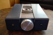
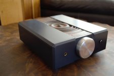
Yes, lovely casework. Where'd you get that wavy top? What is the rest?
I designed and built the whole thing myself. The main case is CNC machined aluminum that is gun metal grey anodized with a bare aluminum volume knob. I modeled the ripples of a drip of water in CAD and then CNC milled the walnut.
I designed and built the whole thing myself. The main case is CNC machined aluminum that is gun metal grey anodized with a bare aluminum volume knob. I modeled the ripples of a drip of water in CAD and then CNC milled the walnut.
Very nice Puck77!
Do you have any more pictures of the build process? What kind of CNC machine are you using?
I am actually planning my second Whammy build and I was thinking of doing some similar casework (machined and anodized aluminum).
I am interested in how you are holding the individual panels together, the usual internal brackets with screws and shallow threaded holes? I was thinking of maybe using magnets or something clever so that the top could be easily removed.
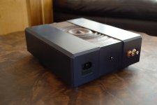
I didn't really take any pics of the build itself. I realize now that I should have! The walls are pocketed on the insides so that I could put through holes in the pocket walls for screws that then mate to tapped holes in the other panels. The board is mounted on standoffs "upside down" to the top of the case. The bottom comes off with 4 screws for easy access to everything. I also cut mounting parts for the switches and headphone jack that mount to the inside of the end panels so that everything can be cleanly mounted so no nuts are visible from the outside.
I cut all the parts on a 3 axis CNC. It's a Hurco.
I cut all the parts on a 3 axis CNC. It's a Hurco.
- Home
- Amplifiers
- Pass Labs
- "WHAMMY" Pass DIY headphone amp guide