Or you can use Visual Analyzer and a soundcard.
It has scope wave generator spectrum analyzer and DVM and it is free!!
Download from here:
Download
Your normal soundcard can probably be used or you can buy this cheap usb device : Behringer uca202:
Behringer U-Control UCA202 – Thomann Danmark
It has scope wave generator spectrum analyzer and DVM and it is free!!
Download from here:
Download
Your normal soundcard can probably be used or you can buy this cheap usb device : Behringer uca202:
Behringer U-Control UCA202 – Thomann Danmark
FYI, acg has got a 60 MHz oscilloscope and the main issue is somewhere in the analogue part - although there is also an issue with the interfacing with the DIX4192.
Last edited:
Made up a cable to swap channels on the filter pcb. The ValveDac LHS now drives the RHS filter, and so on. Also removed R1 on my previous sketch so should be getting roughly double the output voltage previously.
Results:
(1) low output has shifted from left speaker to right speaker and high output from right to left
(2) High output is 0.94Vac...was previously about half that...so this is correct
(3) Low output is still 0.16V...has not doubled and is exactly the same as before other than now being on the opposite speaker.
(4) Still have more than 12Vac between the DC Blocking Caps C32/C31
Am thinking now that the issue is on the dac pcb.
Yes, that sounds logical. Could you measure the AC levels with respect to ground while playing 1 kHz, 0 dBFS on both sides of C31, both sides of C32, and both sides of each of the DC blocking capacitors of the channel that works properly? Maybe we can narrow it down to either C31's side or C32's side then.
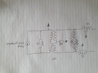
See the attached diagram for how things are currently wired.
I overlooked it at first, but the common-mode termination is missing. Could you add 150 ohm to ground from the centre tap of the primary winding of the transformer on both channels?
To elaborate on post #1824:
The reason why I asked you to measure the AC voltage to ground on both sides of each of the four DC blocking capacitors is that I'm starting to wonder if either C31 or C32 has developed an open connection. Unfortunately the issue that koldby brought up complicates things a bit.
Suppose you measure the voltage to ground at the side of C54 that is connected to C51, R76, U28B and U30A. I'm not sure what reading your meter will give, as there are at least four possibilities:
A. If it only measures the AC component and ignores DC, it will be a few hundred millivolts
B. If it measures the RMS value of the complete signal, AC + DC, it will depend mainly on the DC bias voltage, so you will get a value of the order of 25 V.
C. If it measures the full-wave rectified value of the complete signal, AC + DC, and then applies a correction factor, it will depend mainly on the DC bias times a correction factor of pi/(2 sqrt(2)) ~= 1.1107, so you will get a value of the order of 28 V.
D. If it measures the half-wave rectified value of the complete signal, AC + DC, and then applies a correction factor, chances are it can't handle negative voltages and displays 0 V. When you then swap the leads of the meter, you will see something like the DC bias voltage times a correction factor of pi/sqrt(2) ~= 2.2214, so you will get a value of the order of 56 V.
No matter which case applies to your meter, I hope a 12 V RMS or so AC level on either C31 or C32 will give a noticeably different reading than you get for the other capacitors. It is important to keep RV1 and RV2 centred to keep the DC bias voltages close to each other.
FYI, acg has got a 60 MHz oscilloscope and the main issue is somewhere in the analogue part - although there is also an issue with the interfacing with the DIX4192.
Marcel, did you read acg's posting ?
One thing I did realise is that the old analogue oscilloscope may have developed a fault because it is giving me rubbish and varying readings so it is ditched for now.
Hans
I did, particularly the "for now", which seems to imply that he wants to get it up and running again eventually. In case I misinterpreted that, which of the many PicoScopes has your preference?
For what it's worth, when I get rubbish out of an oscilloscope, it is almost always due to poor contact in the probes. I have five passive probes and none of them are really reliable.
For what it's worth, when I get rubbish out of an oscilloscope, it is almost always due to poor contact in the probes. I have five passive probes and none of them are really reliable.
The scope readings were suddenly 10x smaller in one channel regardless of which probe (there are four probes) was used, and although I could get what I thought was the correct values back using the 10x mag function by that stage it was just an ancillary problem to sort out and best set aside until I had only one confounding problem to solve. Was also having what was probably poor contact issues with them as well.
Would be nice to get the scope back into operation in a way where I am confident it is giving me the correct information, but otherwise something like a picoscope might be appropriate.
Would be nice to get the scope back into operation in a way where I am confident it is giving me the correct information, but otherwise something like a picoscope might be appropriate.
To elaborate on post #1824:
The reason why I asked you to measure the AC voltage to ground on both sides of each of the four DC blocking capacitors is that I'm starting to wonder if either C31 or C32 has developed an open connection. Unfortunately the issue that koldby brought up complicates things a bit.
Suppose you measure the voltage to ground at the side of C54 that is connected to C51, R76, U28B and U30A. I'm not sure what reading your meter will give, as there are at least four possibilities:
A. If it only measures the AC component and ignores DC, it will be a few hundred millivolts
B. If it measures the RMS value of the complete signal, AC + DC, it will depend mainly on the DC bias voltage, so you will get a value of the order of 25 V.
C. If it measures the full-wave rectified value of the complete signal, AC + DC, and then applies a correction factor, it will depend mainly on the DC bias times a correction factor of pi/(2 sqrt(2)) ~= 1.1107, so you will get a value of the order of 28 V.
D. If it measures the half-wave rectified value of the complete signal, AC + DC, and then applies a correction factor, chances are it can't handle negative voltages and displays 0 V. When you then swap the leads of the meter, you will see something like the DC bias voltage times a correction factor of pi/sqrt(2) ~= 2.2214, so you will get a value of the order of 56 V.
No matter which case applies to your meter, I hope a 12 V RMS or so AC level on either C31 or C32 will give a noticeably different reading than you get for the other capacitors. It is important to keep RV1 and RV2 centred to keep the DC bias voltages close to each other.
From the Fluke 287 blurb:
True-RMS AC voltage and current for accurate measurements on complex signals or non-linear loads. AC bandwidth specified to 100 kHz.
A webpage on what Fluke mean by "True RMS"
Shall get to measuring this morning.
I overlooked it at first, but the common-mode termination is missing. Could you add 150 ohm to ground from the centre tap of the primary winding of the transformer on both channels?
Have just re-connected the 180R common-mode termination resistors (and removed the adapter cable to swap filter channels). Did have them originally but removed them for some reason that I cannot remember...I think it was to do with hum. Anyway, they are back and there is no hum and the channels are behaving more logically this morning:
LHS: 0.4350Vac output with 0dBFS 1kHz sine playing through the speakers
8.82Vac across DC Blocking Caps with sine playing
RHS: 0.9200Vac output
1.127Vac across DC Blocking Caps with sine playing
Just for absolute clarity attached is the updated circuit diagram.
Attachments
AC measurements to ground from each end of the DC Blocking Caps:
C53 0.5656Vac 0.5664Vac
C54 0.5640Vac 0.5649Vac
C31 0.5635Vac 0.5621Vac
C32 8.338Vac 8.336Vac
First value is filter side, second value is anode side.
C32 is the outlier.
RV1 is a film pot and does not click at the end of its run like the Bourns cemet pots but I did give it a spin and managed to change the Vac reading from about 7.5Vac-8.4Vac and have now left it at about 8Vac. The C31 reading barely moved across that spin range.
Have been trying to figure out how to measure DC leakage of the DC Blocking cap C32. Had desoldered it and it checks fine for capacitance and ESR on the LCR meter, but DC leakage has been brought up here as perhaps an issue. In the end I desoldered and swapped C32 and C31 on the ValveDac pcb and re-did the earlier measurements.
The 8Vac from the previous post has not followed the capacitor to its new slot, and the new cap in that C32 slot also measures 8Vac, so it seems to me as though the DC Blocking caps are intact and not part of the problem.
Then I swapped the filter channels using the adapter cable from earlier and the loud and soft speakers swapped sides while the Vac readings at the DC Blocking caps all remained the same (8Vac on C32), so still seems as though the filter board is not causing the fault.
Earlier, when one of the initial filter caps failed (C51 or C52) it was easy to test with a DMM because it had no resistance across it. I desoldered one end of C28 and C29 and checked them again and they were not shorted and read their specified capacitance with the LCR meter, however I neglected to check for high ESR so perhaps I should desolder them again to be sure.
So your meter suppresses the DC component while measuring AC voltages, which makes interpreting the levels a lot easier than if it didn't.
C32 itself works fine, as it has the same AC voltage to ground on both sides, like a DC blocking cap should. The same holds for the other DC blocking capacitors.
For some reason, C32 doesn't see any load.
Could you measure the AC signal level at all accessible points from the output side of C32 to the filter board to see if and where the signal disappears? I mean follow the line from C32 to the filter board and if needed via the inductors to the transformer to see if the AC voltage to ground is around 8 V everywhere or drops to a much smaller value somewhere.
The weirdest thing just happened...the low and high output have switched sides. I had everything apart checking continuity in the cable (and various other things) and perhaps I put the cable in this time reverse to how it has gone in previous times, which because of the connectors I am using would switch the problem just as has happened now (from C32 to C53) if there was a dodgy connection in there somehow. It will even tell me which wire is causing the issue, which I obviously need to know because the cable checks out when not connected to anything.
Seriously hopeful right now...
Seriously hopeful right now...

Eureka!
Marcel, I apologise for making this build seem so difficult.
It seems all of my problems along the way were to do with connectors: first the J4 Hirose connector with the FPGA; now with a simple Molex connector between the dac and filter pcbs. The 9 pin connector on one end of the cable has a malformed hole that allows the snap in pin to rotate whenever it wants and thus lose contact. Test the cable on the bench and it is fine however you connect things, put one end on the filter board or the dac board and it tests fine but connect both ends of the cable and it loses contact because the tension of the wire causes that pin in the malformed hole to rotate. A drop of super glue has fixed things.
I usually avoid connectors at all costs prefering a hard solder joint but figured this may have been a tricky build and may have needed to plug things in and out a bit...little did I know they would be the cause of me plugging things in and out quite a bit...ha.
Many thanks to all those who have contributed to the bug finding and in particular to Marcel. Much appreciated.
Last edited:
Excellent news @acg
Now you can tweak the pots for minimum noise and enjoy the music - do let us know what you think.
It looks like a very interesting system you have there.
Now you can tweak the pots for minimum noise and enjoy the music - do let us know what you think.
It looks like a very interesting system you have there.
- Home
- Source & Line
- Digital Line Level
- Valve DAC from Linear Audio volume 13