An externally hosted image should be here but it was not working when we last tested it.
Attachments
My brother!
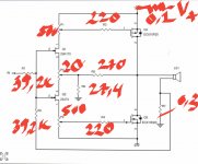
I am Vietnamese. i'm diyer. no trade. I have installed according to the above diagram but the sound is not good. I saw the Chinese selling on ebay. I'm not sure where the diagram is wrong so I'd like to get your opinion.
I am Vietnamese. i'm diyer. no trade. I have installed according to the above diagram but the sound is not good. I saw the Chinese selling on ebay. I'm not sure where the diagram is wrong so I'd like to get your opinion.
Among low-feedback Class A, IMO yes.
The devices have very low gm and are best used with an input stage with plenty of available gain/feedback for the best objective results. I know this isn't the place for objective results but...
The F7 manages to extract quite a lot of performance from these devices, in spite of having low OLG. I can't think of another design that does that so effectively. The Plantfeve amp comes close, but not exactly there.
regarding the Plantefeve amp are you referring to Zenquito?
2A & DIY
Last edited:
I am Vietnamese. i'm diyer. no trade. I have installed according to the above diagram but the sound is not good. I saw the Chinese selling on ebay. I'm not sure where the diagram is wrong so I'd like to get your opinion.
this amp is pretty much impossible to make without selected input JFets and usage of THD Spectra analyzer, while setting working parameters
I am Vietnamese. i'm diyer. no trade. I have installed according to the above diagram but the sound is not good. I saw the Chinese selling on ebay. I'm not sure where the diagram is wrong so I'd like to get your opinion.
Man , this is the only right word I see here 😀
you say you are a Diyer , let's prouve it 😉
and please , let the "Chinese" do/sale what they like to , they will sale you hope when there isn't any ....
.
regarding the Plantefeve amp are you referring to Zenquito?
No i refer to this one: http://jm.plantefeve.pagesperso-orange.fr/zenotron.gif
You can draw your own conclusions from the schematic.
@Danghunglshb
The 3 pots are very interactive. Per ZM, without proper test equipment, very difficult to balance out, requiring much trial and error, patience and time.
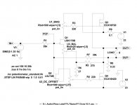
I modeled the attached circuit myself in LTSpice. It appears to basically match yours, so I don't see anything drastically wrong there. I built it using matched input JFETS and supposedly "selected" outputs bought from a European distributor that I did not have the equipment to measure properly.
The amp sounds good, although it's very different from my F6 and closer in sound to my M2x although really not the same. I prefer the F6 overall. If yours sounds really wrong, I suggest you check your wiring. Also, review your trim pot settings based on everything you can glean from this forum.
I suspect that this will never really be an easy DIY project to implement. Inputs, outputs and other components need to be carefully matched. Setup with three interactive variables is difficult at best.
The 3 pots are very interactive. Per ZM, without proper test equipment, very difficult to balance out, requiring much trial and error, patience and time.
I modeled the attached circuit myself in LTSpice. It appears to basically match yours, so I don't see anything drastically wrong there. I built it using matched input JFETS and supposedly "selected" outputs bought from a European distributor that I did not have the equipment to measure properly.
The amp sounds good, although it's very different from my F6 and closer in sound to my M2x although really not the same. I prefer the F6 overall. If yours sounds really wrong, I suggest you check your wiring. Also, review your trim pot settings based on everything you can glean from this forum.
I suspect that this will never really be an easy DIY project to implement. Inputs, outputs and other components need to be carefully matched. Setup with three interactive variables is difficult at best.
Attachments
No capacitor!
I'm not sure if you were referring to my post, but I wasn't actually replying to you. Of the multiple conversations on this thread, like others on the forum, I was replying to marconi118.
It had nothing to do with your problems, which were being handled by other participants. That being said, the whole schematic you posted is incorrect. If you feed that into the simulator, you'll see you can't hit the CLG targets due to the low transconductance of the output stage. It is not going to sound good at all.
lqham did some extensive work on modelling the circuit in the beginning of the thread. It's conceptual, but you can start there to understand what this circuit should look like. There's plenty of hints dropped in by a bunch of folks, but a few days on a sim and you should be able to get something pretty solid out of it. There's no ready schematics yet, but there might be some coming in the future.
As ZM alluded to, you can't use just any JFETs, you have to select them for the Idss range you designed with in your specific sim, which is tricky because you need to balance input stage gm with the need to quickly discharge the gate capacitance, which limits the possible Idss values.
I think I've said more than I should have, but you can use all of this as a starting point. Or you could build the Cubie, or the Zentoro, or literally anything else using your devices, or wait for the official release if and when there's one.
Thank you
There is a problem that Jfet's Vds are very high so they are hot, if used for a long time can die. Vgs of 10P20 is always larger than Vsg of 10N20 even though it has been calibrated to make the speaker output voltage zero, the voltage of pin D of J and K is balanced.
There is a problem that Jfet's Vds are very high so they are hot, if used for a long time can die. Vgs of 10P20 is always larger than Vsg of 10N20 even though it has been calibrated to make the speaker output voltage zero, the voltage of pin D of J and K is balanced.
Last edited:
DangHung, the F7 is in a current production of FirstWatt. All of us here loves Papa too much such that it feels unethical to help anyone makes a clone.
ECX series from Exicon don't have the same dynamic range as 2SK1058 and 2SJ162. You have to use +32V rails or use the ECW series from Exicon they are better. I use ECW with 32V rails and they sound excellent.
Jfets don't have to be matched. Use J74 with Idss 3ma higher then K170
For gate resistors 47R is enough.
Jfets don't have to be matched. Use J74 with Idss 3ma higher then K170
For gate resistors 47R is enough.
You want to make money? Wrong place here.
Laughed so bad on this one Gerd ha-ha-ha. By this post you can obviously recognize a seasoned DIYer -- we only spend money here 🙂
Good that at least you can laugh at my comment.....
:--))
I might have overreacted a bit, but I had no good feeling when someone first shows an Ebay link where you can order F7 boards and later publishes the fitting circuit without great comment.
Have a good weekend PKI and spend some money in your new build....
:--))
I might have overreacted a bit, but I had no good feeling when someone first shows an Ebay link where you can order F7 boards and later publishes the fitting circuit without great comment.
Have a good weekend PKI and spend some money in your new build....
ECX series from Exicon don't have the same dynamic range as 2SK1058 and 2SJ162. You have to use +32V rails or use the ECW series from Exicon they are better. I use ECW with 32V rails and they sound excellent.
Jfets don't have to be matched. Use J74 with Idss 3ma higher then K170
For gate resistors 47R is enough.
Thank so much!
If you use 32v voltage, you can damage the jfet. can use 2k resistors to the D pins of the jfet.
If you use 32v voltage, you can damage the jfet. can use 2k resistors to the D pins of the jfet.
No Jfets are ok up to 40V. I've been running them at 32V for a year no problem
Use lower Jfets with lower Idss 5 to 8 ma
Use lower Jfets with lower Idss 5 to 8 ma
For a sanity check, we simulated a circuit based on the results from the previous analysis.
Input voltage is 1V, 1kHz.
Output voltage across load :
1R 5.37V
2R 5.39V
4R 5.40V
8R 5.41V
16R 5.41V
At 1W, 1kHz into 8R
H2 0.056%
H3 0.0013%
If R1=R2=3.9k (Zin~10k at 8R load), -3dB bandwidth ~ 1.3MHz
If R1=R2=39k, and input is connected to Gnd with a 11k resistor, -3dB BW ~ 130kHz
I guess that is not too far off.
🙂
Cheers,
Patrick
Patrick,
Must be something wrong with your calculation. The original F7 has R1 and R2 at 39K according to some pictures from inside, but the specified input impedance of 10K. For those values input impedance is 100k according to your calculations. Could they be 3.9K in the original?
- Home
- Amplifiers
- Pass Labs
- First Watt F7 review