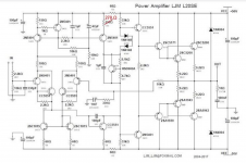
LJM mentions it's OK to use less then +-60v rails and I've got an Onkyo adm21 that I was thinking on using the chassis, heatsink, and transformer. The transformer has 43-0-43, 33-0-33 (not used), 18-0-18, and 5vac. The schematic for this amp shows +-57.8 rails and it uses 2sc5200, 2sa1943 (just one of each for each channel.
Is the L20SE going to live with this much rail voltage?😕
Is the L20SE going to live with this much rail voltage?😕
Attachments

L15D, L20D, L25D
I'd like to ask whether the CP1 22uF input capacitor is a part od the negative feedback circuit in those amps?
If the answer is yes, CP1 can't be shorted even if there is no Vdc at the input.
I think the answer is YES.
I'd like to ask whether the CP1 22uF input capacitor is a part od the negative feedback circuit in those amps?
If the answer is yes, CP1 can't be shorted even if there is no Vdc at the input.
I think the answer is YES.
You can consider using l20.5
L20.5 is an upgrade of l12-2.
Sorry but I can't relate with this statement. L20.5 has only 6 small signal transistors but L12-12 and L20SE have 12 small signal transistors on PCB (excluding output, drivers and bias). Even MX50 ones have 10 transistors with two extra driver size transistors (which makes 12 actually). How come L20.5 regarded as an "upgrade" despite reduction in complexity?
Sorry but I can't relate with this statement. L20.5 has only 6 small signal transistors but L12-12 and L20SE have 12 small signal transistors on PCB (excluding output, drivers and bias). Even MX50 ones have 10 transistors with two extra driver size transistors (which makes 12 actually). How come L20.5 regarded as an "upgrade" despite reduction in complexity?
Did you miss the two tiny dual surface mount transistors? (Four more?) They are very small six pin surface mount packages.
Did you miss the two tiny dual surface mount transistors? (Four more?) They are very small six pin surface mount packages.
I didn't notice those tiny smd transistors until you pointed out. So we can assume that 10 small transistors at best. I have to apologize in this regard.
One can probably not generally gauge the quality of an amplifier by the number of transistors - take Hood1969 for instance. However, I believe the L20SE is one of LJMs favourites?
L20SE with TTA/TTC Toshiba's looks promising to me too, except those high voltage transistors (5551/5401) at input stage.
The 5551 and 5401 might be a good choice for certain usages (locations/purposes) in power amplifiers and not other locations.
What's the magic of 2N5551 / 2N5401?
What's the magic of 2N5551 / 2N5401?
Surely it is the quality and implementation of the design NOT how many transistors or other components used. Many would argue that a Class A design sounds best and they are usually low component count. Yes
Surely it is the quality and implementation of the design NOT how many transistors or other components used. Many would argue that a Class A design sounds best and they are usually low component count. Yes
But the problem is, we are not discussing single ended class A topologies here. LJM boards are tend to be class B style boards and such topologies must retain a degree of complexness in order overcome obstacles on their way. There is no free lunch here. Invention and evolution of opamp IC's is a good example.
LJM mentions it's OK to use less then +-60v rails and I've got an Onkyo adm21 that I was thinking on using the chassis, heatsink, and transformer. The transformer has 43-0-43, 33-0-33 (not used), 18-0-18, and 5vac. The schematic for this amp shows +-57.8 rails and it uses 2sc5200, 2sa1943 (just one of each for each channel.
Is the L20SE going to live with this much rail voltage?😕
I would use the 33-0-33 rails on your transformer for an ~ 45-0-45 VDC rails .
Modules will run much cooler and have the added ability of easily driving much lower loads . Even if your speakers are rated at 8e , there may be points where they drop to about 3e .
"Power 200W 8R 350W 4R at DC + - 65V
Performance parameters:
Dual power supply range :+/-DC18V- +/-DC65V. (recommned +/-50V)"
If you decide to use the lower voltage windings, you could check the winding cable thickness to ensure the necessary current is available, otherwise rail voltage will drop considerably under load. Instead you could consider regulating the 57.8V down to 50V. Will generate bit of heat, but rails will be less noisy and it might save you some (expensive) power supply caps, if there are not enough originally in the Onkyo.
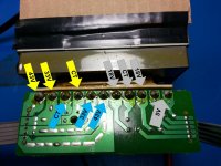
Hey guys I have found the reason for the one l20.5 not heating up!
The 10uf ceramic capacitor in the bias circuit is broken. I bet this is often the case, seeing that the man has replaced it for bipolar electrolytic in the newest incarnations.
The 10uf ceramic capacitor in the bias circuit is broken. I bet this is often the case, seeing that the man has replaced it for bipolar electrolytic in the newest incarnations.
Hey guys I have found the reason for the one l20.5 not heating up!
The 10uf ceramic capacitor in the bias circuit is broken. I bet this is often the case, seeing that the man has replaced it for bipolar electrolytic in the newest incarnations.
yes. I found that some ceramic capacitors would be damaged.
I have replaced it with BP electrolytic capacitor.😀
Even a blind chicken will find some corn😀
Can you tell me what power rating I can use for damaged 0,05 ohm resistors? If I destroy some again it would be good to know.
I just bought the new L20,5 with Onsemis and BP electrolytics. This time I will not change any components. I had the feeling that it was useless doing so, thank you for confirming.
I believe that I have been having HF oscillations, judging by how sensitiv to cable placement it is. Even putting the cover on the chassis changes the tonality of the hum, I have headphones connected directly to the output with no attenuation. I cannot hear hum or noise from loudspeakers though. I get total silence when putting the signal input cable UNDER the filter capacitors and as I have understood it this is not a good solution due to magnetic field when playing music.
Can increasing bias ,like Berlusconi did ,stop the oscillation and make the amp less sensitive to cable placement and metal objects? Is the finished amp with case that you sell the best possible layout, or can one use disipante style case with equal success?
Thank you for very addictive kits and all the fun 🙂
yes. I found that some ceramic capacitors would be damaged.
I have replaced it with BP electrolytic capacitor.😀
How long ago?
I just bought the new L20,5 with Onsemis and BP electrolytics. This time I will not change any components. I had the feeling that it was useless doing so, thank you for confirming.
Interesting. Almost a year ago I bought an L20.5 with D1047/B817 and I had to replace the outputs with genuine 2SC5200/2SA1943 because the stock outputs blew on first power up. (Blew on one of the two amps and the other was ok.) That was not the first LJM amp with the outputs to blow either. Never had a problem after replacing the outputs with genuine Toshiba 2SC5200/2SA1943. I just assumed that the stock D1047/B817 were fake junk.
But I really could not believe a quad output pair L20.5 blowing up on first power up without even a signal yet. When I debugged and started to repair it that L20.5 same amp drove my speakers for a couple weeks with just a single 2SC5200/2SA1943 pair installed.
I can identify with your experience with this kit, after all I torched my first set of boards possibly three times 😀
The first time It happened I plugged in my silent Switcher powered preamp to a charger and there went the output stage. I was using headphone probes direct on the L20.5 output. It hurt my ears quite a lot. I think that maybe an amp should survive such accidents.
One thing that was suboptimal,
Mal was the drilling of the driver heatsink. Two of the transistors were not flat against it due to massive burr around the threaded holes. I think this was a cause of instability.
My second set of boards Imremoved all components to see if the transistors were matching and also resistors and so on. I found the components to be well matched, I did not expect that based on what I have read here. So why did not one board warm up? Yep, broken ceramic capacitor. At least I have a lifetime supply of Kec transistors now 😉 Next time I will look for a simple explanation before I go on a parts shopping spree😀
By the way the Kec transistors in the kit are 100% like the ones I got in genuine tubes from Reichelt.de
Interesting. Perhaps I will try opening the failed KEC. I have never had a genuine Toshiba fail but I have had several bad KEC experiences. Each time it was one side that went and was very rapid on first power up. And each time the other side was perfectly fine.
In the case of the MX50x2 I took the surviving side apart to measure each component and I found a couple badly matched components. For the L20.5 pair most of the output transistors were well matched but a couple were not.
In the case of the MX50x2 I took the surviving side apart to measure each component and I found a couple badly matched components. For the L20.5 pair most of the output transistors were well matched but a couple were not.
- Home
- Vendor's Bazaar
- LJM Audio