By the way, try using steel. Steel tins (such as cookie tins) can be helpful for a little bit of shielding.
I mention this in case you are not aware that you might not get much of a result with aluminum.
Unrelated to shielding but related to SMPS: In my SMPS experiments I found that a spectrum of the SMPS output (when the amplifier was drawing 100W) showed a wide smeared out set of powerline harmonics. Presumably that is due to the increased powerline ripple on the SMPS input filter capacitors under heavy load and then modulated by the TL494 based SMPS.
Without load (idle class AB) that noise was not apparent and I initially missed it.
The same class AB amplifier with a regular transformer/bridge/cap supply had a significantly cleaner output spectrum (at near full power) than with the SMPS. I had expected the opposite due to the regulation of the SMPS.
I went back to a regular transformer/bridge/cap supply for now. I might try again with a capacitance multiplier after the SMPS but I have found that power capacitance multipliers are not so simple either.
SMPS is not pure DC voltage.
It is actually made up of very high voltage PWM voltage. About 200 v. 100KHZ
It consists of the output capacitance. Inductance. It attenuates high frequency voltage to very low voltage. Close to DC voltage.
But. It still has high frequency PWM voltage.
So a lot of times. SMPS to the power amplifier. It is possible to damage the Robel resistance.
Even power tube.
SMPS is not pure DC voltage.By the way, try using steel. Steel tins (such as cookie tins) can be helpful for a little bit of shielding.
I mention this in case you are not aware that you might not get much of a result with aluminum.
Unrelated to shielding but related to SMPS: In my SMPS experiments I found that a spectrum of the SMPS output (when the amplifier was drawing 100W) showed a wide smeared out set of powerline harmonics. Presumably that is due to the increased powerline ripple on the SMPS input filter capacitors under heavy load and then modulated by the TL494 based SMPS.
Without load (idle class AB) that noise was not apparent and I initially missed it.
The same class AB amplifier with a regular transformer/bridge/cap supply had a significantly cleaner output spectrum (at near full power) than with the SMPS. I had expected the opposite due to the regulation of the SMPS.
I went back to a regular transformer/bridge/cap supply for now. I might try again with a capacitance multiplier after the SMPS but I have found that power capacitance multipliers are not so simple either.
It is actually made up of very high voltage PWM voltage. About 200 v. 100KHZ
It consists of the output capacitance. Inductance. It attenuates high frequency voltage to very low voltage. Close to DC voltage.
But. It still has high frequency PWM voltage.
So a lot of times. SMPS to the power amplifier. It is possible to damage the Robel resistance.
Even power tube.
Although it has several advantages, a SMPS radiates a lot of HF that can be “captured” by circuitry. If the SMPS is not already shielded, add a sheet of u-metal between SMPS and amplifier(s). To test, ground a small section of u-metal, cover it with tape (to avoid silly accidents), put a scope on the amp output and position the sheet between SMPS and amp. Pretty dramatic effect on my MX50SE 🙂 incidentally, any amp construction should be checked with a scope, with and without load, at low and high signal levell, varying frequency and waveform. Oscillation, sine wave crossover issues, and/or overshoot (use e.g 5khz square wave) will have a detrimental effect on sound (hiss, distortion).
SMPS is not pure DC voltage.
It is actually made up of very high voltage PWM voltage. About 200 v. 100KHZ
It consists of the output capacitance. Inductance. It attenuates high frequency voltage to very low voltage. Close to DC voltage.
But. It still has high frequency PWM voltage.
So a lot of times. SMPS to the power amplifier. It is possible to damage the Robel resistance.
Even power tube.
Thanks Kozard for a response.
Actually I have measured available surface of heatsink for new boards and have available 3 choices left: L7, MX50SE, MX50X2.
It was complains that L7 sounds not very good at lower volumes, which is most important thing for me, as I'm listening music most of the time at reasonably quiet and comfortable level, within 1W range. Only 4 times in a year I need from amplifier 25w-50w per channel.
Connected to bookshelf speakers Triangle Titus ES. 8ohm nominal (4ohm drop in resonance freq). 60W nominal, max peak 120w.
MX50SE, L20.5 I recommend it. 、
I have built both, they are great! The L20.5 is the best amplifier I have ever had. It was a challenge to get it work right at +/-52V, but It was worth every effort!
I have already bought a second pair. Is bridging L20.5 a good idea?
I have already bought a second pair. Is bridging L20.5 a good idea?
Re. the SMPS discussion, my two MX50SE have been running fine with one of those for a long time now. Dead quiet and sound great - and they run cool on relatively small heatsinks - Kudos to LJM for that design! But, worrying about HF etc, the current project has 2x30,000 uF on the rails w. slow start circuit - while killing all ripples etc they also give a bit of extra transient resources. Also this project is totally hum- and and noise-free, partly thanks to the two SMPS - Re. the L20.5 suggestion - current (2019) version is no 10, correct? But the older one is preferred?
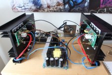
Hello my test setup has been running since:
Power supply 2 x 54 volts + Softstart.
I reduced the input sensitivity by adjusting the resistance and the potentiometer is no longer required.
No background noise perceptible.
I'm curious how it sounds when it has been running for a while.
Power supply 2 x 54 volts + Softstart.
I reduced the input sensitivity by adjusting the resistance and the potentiometer is no longer required.
No background noise perceptible.
I'm curious how it sounds when it has been running for a while.
Attachments
Last edited:
I have built both, they are great! The L20.5 is the best amplifier I have ever had. It was a challenge to get it work right at +/-52V, but It was worth every effort!
I have already bought a second pair. Is bridging L20.5 a good idea?
Hi,
can you describe to us what the challenge was for the fit?
One board got hot, the other not. It was oscillating I guess. I started fiddling around, made some mistakes I guess and burned the boards. Installed replacement boards, one board got hot the other not. Bought a sh-load of transistors from reichelt.de and matched them. Installed potentiometer to adjust IQ. Boards are now equally hot and the amp does not oscillate anymore.
I am not sure what solved the problem since I did this to the boards that I accidentally torched. I think setting quiescent current might have been the important thing.
Will experiment with my untouched boards to confirm at some point.
I am not sure what solved the problem since I did this to the boards that I accidentally torched. I think setting quiescent current might have been the important thing.
Will experiment with my untouched boards to confirm at some point.
My L20.5 burned on first power up with the stock output transistors. I even had very small fast blow fuses (for first power up) but even that was not fast enough. I have had this with other LJM designs including MX50X2. I question the quality and SOA of the stock D1047 outputs in these boards...
After replacing with genuine Toshiba 2SC5200/2SA1943 I have had any problems...
After replacing with genuine Toshiba 2SC5200/2SA1943 I have had any problems...
Hello my test setup has been running since:
Power supply 2 x 54 volts + Softstart.
I reduced the input sensitivity by adjusting the resistance and the potentiometer is no longer required.
No background noise perceptible.
I'm curious how it sounds when it has been running for a while.
What do you like better, SMPS or brute force?
excuse me ,
what means "brute force " ?
Unfortunately, I don't have a classic power supply for comparison, but I really like the Narin Fender switching power supply.
I already installed this in my L15D back then, which still works great and sounds fantastic
what means "brute force " ?
Unfortunately, I don't have a classic power supply for comparison, but I really like the Narin Fender switching power supply.
I already installed this in my L15D back then, which still works great and sounds fantastic
One board got hot, the other not.
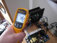
My two L20.5 show the same phenomenon:
The left amplifier / heat sink heats up to around 40 degrees, the right only 22 to 25 degrees.
Question to LJM:
For me it is no coincidence that two people have the same phenomenon.
Is there a system behind it?
A -> Hot B -> cold?
The L20.5 has only one PCB so both are the same. Mine have the exact same temperature but that is because I installed a trimmer (comes with fixed bias) and I measured and set the bias.
Thanks kozard
Yes I followed your instructions on how to set QC a few pages back!
Thank you very much for that 😀
Could not have done it without your help.
Yes I followed your instructions on how to set QC a few pages back!
Thank you very much for that 😀
Could not have done it without your help.
Actually, on one of the boards I got the silk screen says 1k1 on it for the resistor that was substituted for a potentiometer, on the other it says 1k. Seems there are different versions and that they get sent out randomly.Are the PCB layouts the same or symmetrical? Did you check for oscillation
with a scope?
LJM said QC does not matter for the sound of this amplifier and that it can be different than advertised.
LJM L20SE 2004-2018
Just starting to build a pair of these. I'm using a 30-0-30 300va toroid and one or maybe two Rectifier Filter Power Supply Board w Speaker Protection 4x50V/6800UF on each board.
One question about multi turn pot for bias control. I've built the MX50SE and did the bias pots...glad I did. On the L20SE boards I received, R-17 is 8.2k and C-4 and C-8 are 10uf/50v NP. Also I noticed C-6, 7, 9 and 10 are 220uf / 80v.
Do I leave out the 8.2k and put in a 10k multi-turn? That's what I did on the MX50.
Older home audio amplifiers have a bias pot and I'm comfortable doing any mods to make this as nice sounding as possible.
Any help would be very much appreciated before I get too far along with the build.
Attachments
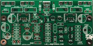
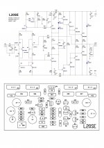
Question... The kits I received are using NP 10uf electrolytic caps for C4 and C8. Not much room there! The schematic posted by Eliseu shows a 1uf in these locations. So my Question is.. OK to use 1uf Metallized Polyester Film Capacitor in these locations? They sure would fit better.
Thanks all
Thanks all
- Home
- Vendor's Bazaar
- LJM Audio